Line welded joints are required for a stress analysis of welds. If you define a weld for a line in a surface model, the stresses of this weld are generated using the design add-on -for-rfem-6/design/stress-strain-analysis Stress-Strain Analysis. Thus, you directly obtain the stresses for the weld design for the selected weld type.
Base
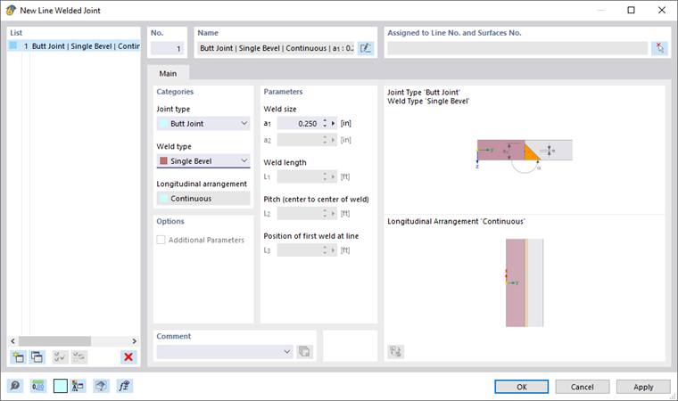
In the General tab, you define the weld type and set its parameters.
Categories
In this dialog section, specify the weld that is available. The types, including parameters, are displayed in the dialog graphic.
Joint Type
The following joint types are available for selection in the list:
- butt joint
- Corner joint
- Lap Joint
- Tee Joint
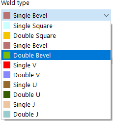
Weld Type
Depending on the joint type, the list offers different options to perform weld designs.
Weld Arrangement
The list provides two options for arranging the weld axis system:
- Contrary to surface normal (-z)
- Surface Normal (+z)
This allows you to control whether the weld longitudinal axis j is oriented in the direction of the positive surface normal of the connected surface (as shown in the dialog graphic above right) or in the opposite direction.
Longitudinal arrangement
Currently, line welded joints can only be arranged 'Continuously' over the entire line length.
Parameters
In this dialog section, enter the 'Weld size' to define the weld thickness. The 'Weld length' is taken from the line length.
Assigned to Line No. and Surfaces No.
Define the line and the surface where you want to arrange the weld. You can use the
![]() you can define the objects graphically.
you can define the objects graphically.
Line welds can only be applied to surfaces with one of the following Material Types type:
- Base
- Steel
- Metal
- Aluminum