The calculation of the deformation is based on this first article of this series.
Wall Stiffness
The stiffness of a wall is calculated under a unit load for 1 kN. You can find more information about the equations used here in the reference literature [1], as well as in the previous article of this series mentioned above.
Example:
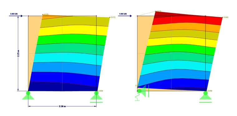
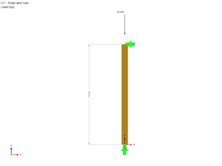
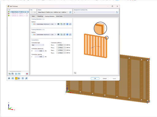
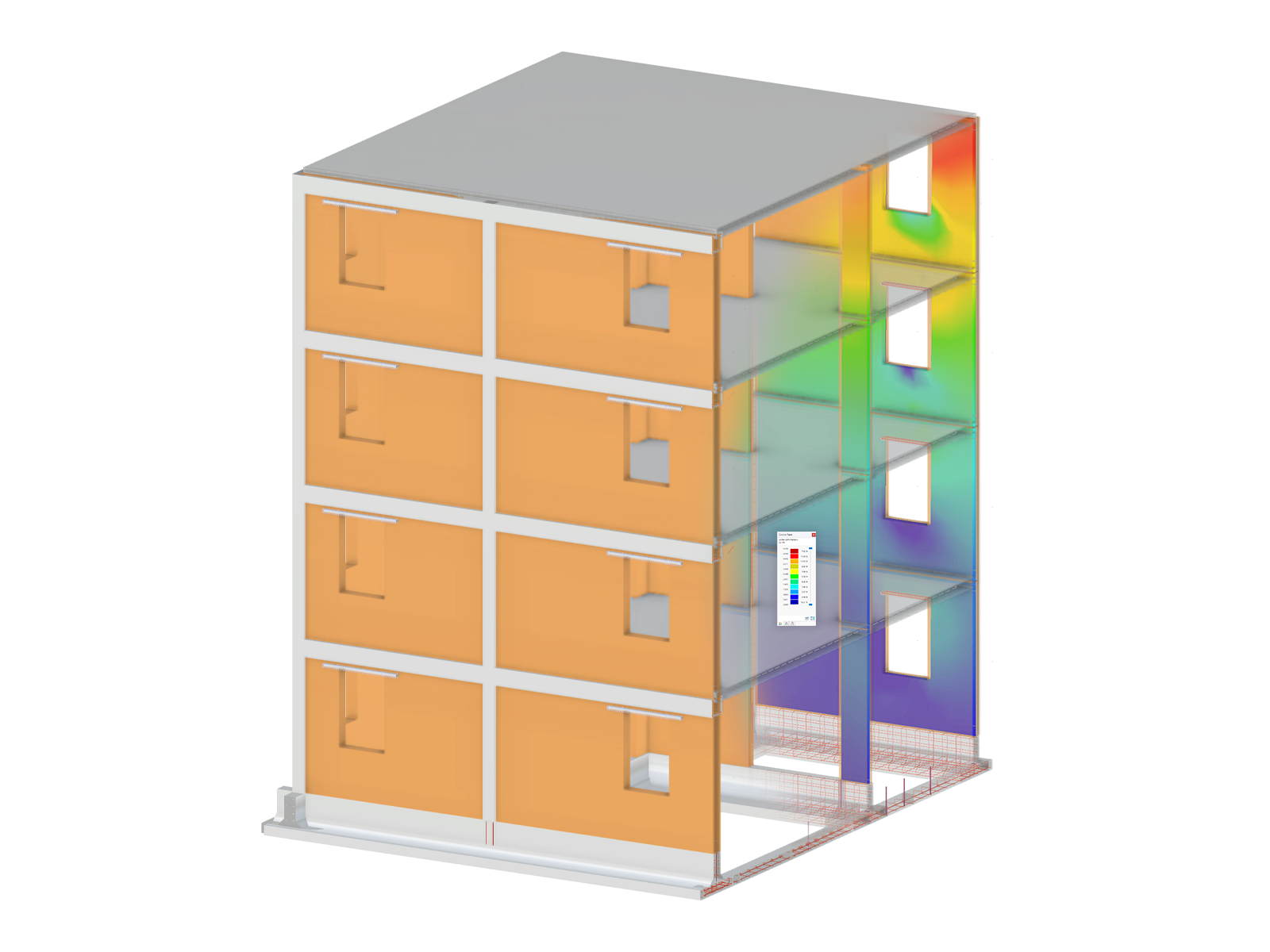
The calculation of the stiffness is performed using a simple example with the dimensions shown in Image 01.
Structure:
- Wall length l = 2.50 m
- Wall height h = 2.75 m
- Stand C24 6/12 cm, ρm, T = 350 kg/m³
- Cladding OSB 3, t = 18 mm (one-sided), ρm,O = 439 kg/m³, G = 108 kN/cm²
- kser = 159 N/mm
- bE = b + t = 12 cm + 1.8 cm = 13.8 cm
- Clamping d = 1.5 mm, t = 45 mm
- Clamping distance av = 60 mm (single row)
- Grid = 62.5 cm
- Tie rod with 10 nails of diameter 4.2 mm nailed
- FE mesh size is 1.3 m. (4 elements per panel)
Stiffness:
Yielding of fastener (clamping)
Yielding of cladding
Yielding of ribs
Yielding of anchor
Sum of yieldings (calculated without the tie rod)
Conversion into an effective area:
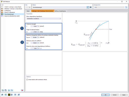
The calculated stiffness is converted into an effective orthotropic panel stiffness. Read this technical article for background information about the orthotropic material model.
Normal stiffness component
Shear stiffness in the panel plane
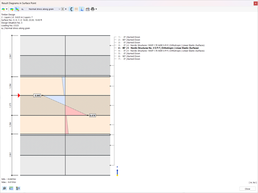
The tie rod can be defined directly in RFEM as a linear elastic spring with the calculated spring stiffness of 6,879.9 N/mm. The comparison of the deformations is shown in Image 01. The differences can also be seen in Model 1 attached to this article.
For a three-dimensional calculation, this method shows the problem of defining the panel bending stiffnesses. This is described in more detail in the technical article on orthotropic material models mentioned above.
Instead of displaying the stiffness of the timber panel wall by means of surfaces, a method for converting the calculated yielding into a line release is shown below.
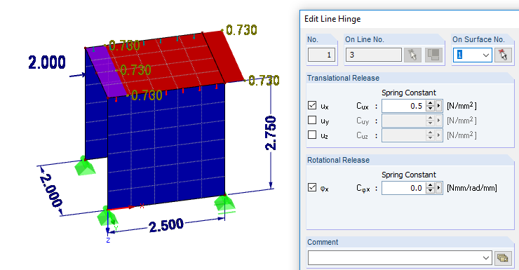
The advantage here is that the surface properties of the model can be assumed to be rigid.
Summary
In this article, the calculation of a timber panel was shown using an effective orthotropic surface. The tie rod can be defined directly as spring stiffness. For a linear two-dimensional calculation of the system, the results correspond very well with the manual calculations in [1]. Thus, a real design with the loads from a stiffening calculation can be performed. The model for the example calculation can be found below, under Downloads.
Another option was the conversion of yielding into a linear spring of the line. For spatial models, this method is more suitable because it largely excludes the influence of plate bending as well as bending in the panel plane. The model can also be found under Downloads.
The next article will show the stiffening of a floor plan in 2D as well as the design of wall panels in 3D.


![RSTAB 9 results - warping moment Momega [kNm]](/en/webimage/047737/3730153/MTsec.png?mw=350&hash=40c7b896b7ecb6c898b763109dcec0b2a330f9f4)
![RSTAB 9 results - secondary torsional moment MTsec [kNm]](/en/webimage/047736/3730151/MTsec.png?mw=350&hash=40c7b896b7ecb6c898b763109dcec0b2a330f9f4)
![RSTAB 9 results - primary torsional moment MTpri [kNm]](/en/webimage/047735/3730144/MTpri.png?mw=350&hash=2363903e71565c33f1897548cd3f9920f0bc53ba)
.png?mw=512&hash=4e74affa9ad0c7b703151c5085ac9b8e59171c23)


.jpg?mw=350&hash=8f312d6c75a747d88bf9d0f5b1038595900b96c1)


.png?mw=600&hash=49b6a289915d28aa461360f7308b092631b1446e)


