The calculation of the wall stiffnesses refers to the second article of this series.

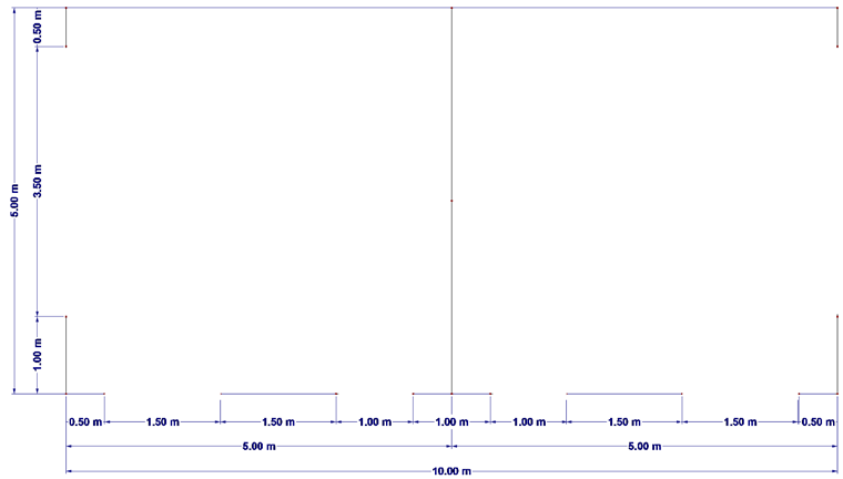
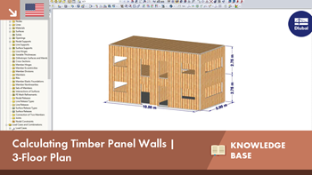
Ground Plan
Due to its different stiffness, the wall stiffness has a considerable influence on the total deformation of the floor plan. Furthermore, the asymmetrical arrangement of the walls also influences the deformation of the building.
Usually, this effect is taken into account by the stiffnesses of a 2D position.
Example
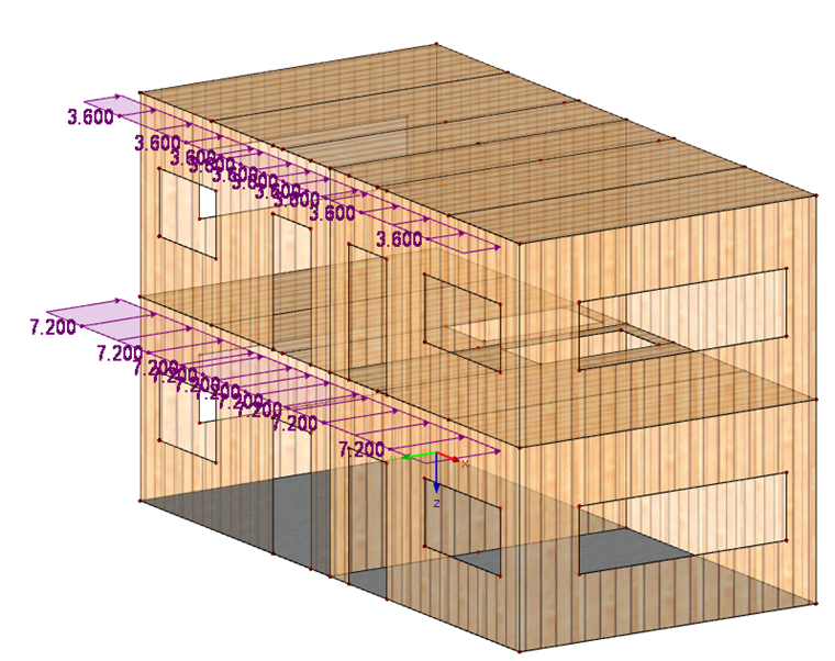
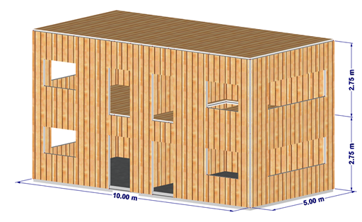
This effect is demonstrated on a simple two-story building. The building has a regular floor plan. Further information on minimum stiffening criteria can be found in [1].
Structure:
- Ground plan = 5 m ⋅ 10 m
- Simplified calculation, windows are excluded story-high.
- A tie rod is placed on each end of the wall.
- Wall structure and stiffnesses as described in Article Two of this series.
- FE mesh size = 1.5 m
Loading:
- Self-weight and structure = 2 kN/m²
- Wind load in the global y-direction
- WZ2
- Height = 100 m above sea level NN
- we+d = 0.46 + 0.74 = 1.2 kN/m²
- We,d = 1.2 kN/m² ⋅ 3 m = 3.6 kN/m
Combination:
- CO1 = 1.0 LC1 + 1.5 LC2
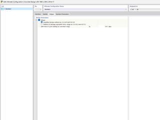
Wall Stiffnesses:
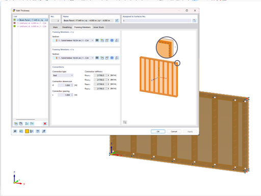
This results in four different wall lengths. To simplify it, the wall stiffnesses are calculated for equivalent members. The determination of the stiffnesses is the same as in the previous article.
| Wall | Length [m] | Modulus of Elasticity [kN/cm²] | D66/D77 [kN/cm] | G-Modulus [kN/cm²] | D88 [kN/cm] | Stiffness Support [kNcm/rad] |
|---|---|---|---|---|---|---|
| 1 | 0.5 | 792 | 9,504 | 0.47 | 6.5 | 64,499 |
| 2 | 1.0 | 396 | 4,752 | 0.80 | 11.0 | 257,995 |
| 3 | 1.5 | 264 | 3,168 | 1.04 | 14.3 | 580,489 |
| 4 | 2.5 | 158 | 1,901 | 1.36 | 18.8 | 1,612,469 |
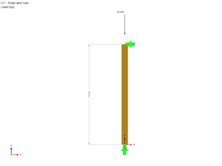
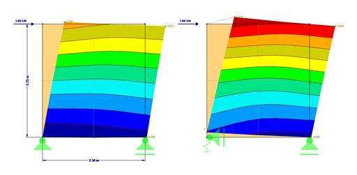
The wall stiffnesses are calculated for each of these four wall lengths. For this purpose, each wall is loaded with a unit load of 1 kN. Since wall lengths over 2.5 m with a height of 2.75 m cannot be manufactured, the middle wall is divided in the middle.
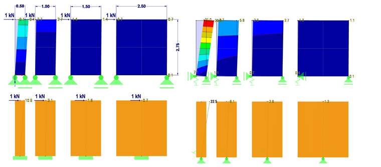
In the attached RFEM Model File 1, the deformations for all wall lengths are calculated as surfaces and member results. The deformation is calculated without a wall anchor in the upper part of the model, and with a wall anchor in the lower part. The deformations are also compared in Figure 04.
A stiffness is calculated for each wall from the determined deformations of the individual walls.
As an example, the following stiffness is obtained for wall 1 with a length of 50 cm:
C = F /u = 1 kN / 22.5 mm = 0.044 kN/mm
c = F / l ⋅ C = 1 kN / 0.5 m ⋅ 0.044 kN/mm = 0.088 N/mm²
For all walls:
1st wall | l = 0.5 m | c = 0.088 N/mm²
2nd wall | l = 1.0 m | c = 0.164 N/mm²
3rd wall | l = 1.5 m | c = 0.230 N/mm²
4th wall | l = 2.5 m | c = 0.333 N/mm²
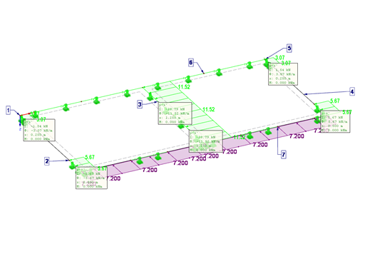
These stiffnesses are assigned to the respective line support in the floor plan (see Figure 05). The floor plan can be found in the attached RFEM Model File 2.
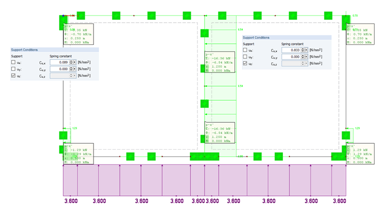
Due to the symmetrical building, there is no rotation of the building. This article explains this in more detail. The attached video shows how the horizontal forces develop in an asymmetrical floor plan against the load direction.
Summary
This article showed the calculation, by floor, of timber panel buildings. The stiffnesses can be determined by means of surface or member elements. Elasticities resulting from an anchorage are taken into account.
Use the attached Excel file to reproduce the calculation of the examples.
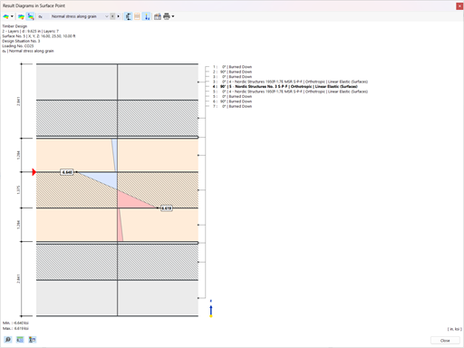
The final part of this series will follow, which shows the design of the forces determined from the line support reactions (see Figure 05).


.png?mw=350&hash=117ad3f33c60ab58cde72c606f62ba73be0be9f3)


.png?mw=350&hash=181c15a9942b40897a0a04b6dfdbfeb6ab39288c)


.png?mw=512&hash=4e74affa9ad0c7b703151c5085ac9b8e59171c23)
.jpg?mw=350&hash=8f312d6c75a747d88bf9d0f5b1038595900b96c1)


.png?mw=600&hash=49b6a289915d28aa461360f7308b092631b1446e)


