In the following example from the Steel Structures Yearbook 2009 [3], the cross-section design for a single-span beam with a thin-walled, cold-formed C-section is performed under normal force loading. The C-section is modeled in SHAPE-THIN and then designed in RF-/STEEL Cold-Formed Sections.
System
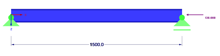
System and loading are shown in Figure 01.
Material
S 355 EN 10025-2
E = 210,000 N/mm²
G = 80,769 N/mm²
ν = 0.3
fy = fyb = 355 N/mm²
γM0 = γM1 = 1.00 (design according to CEN)
External Dimensions
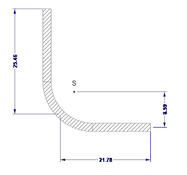
The external dimensions of the cross-section are shown in Figure 02.
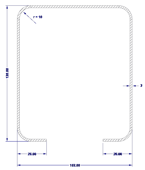
H = 102 mm (web height)
b = 120 mm (belt width)
c = 26 mm (lip length)
t = 2 mm (steel core thickness)
Notional Flat Widths
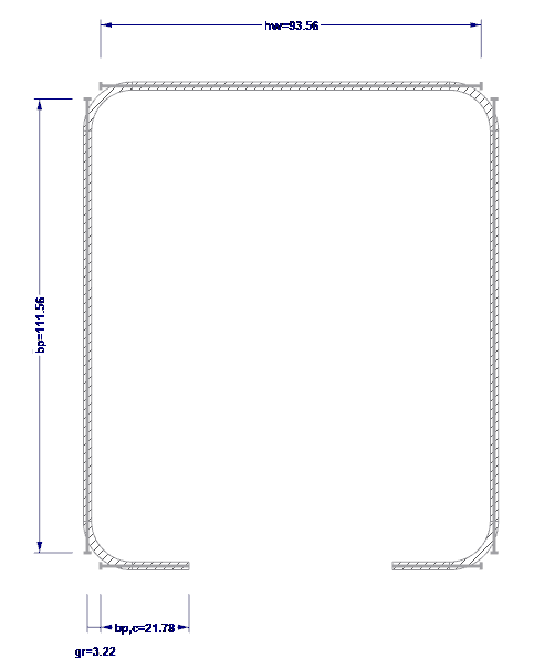
The notional flat widths are determined according to [1], 5.1. The notional flat widths are shown in Figure 03.
Checking Width-Thickness Ratios
The width-thickness ratios are checked according to [1], 5.2 (1).
b/t = 120/2 = 60 ≤ 60
c/t = 26/2 = 13 ≤ 50
H/t = 102/2 = 51 ≤ 500
The width-thickness ratios are met.
Checking Stiffener Dimensions
The stiffener dimensions are checked according to [1], 5.2 (2).
0.2 ≤ c/b = 26/120 = 0.22 ≤ 0.6
The lips can be applied as stiffeners.
Checking the Angle Between the Stiffener and the Planar Element
The angle between the stiffener and the planar element is 90° within the limits of 45° and 135° mentioned in [1], 5.5.3.2 (1).
Determining the Effective Cross-Section
For steel sections that are not subjected to double symmetry and subjected to compression, the centroidal position of the effective cross-section shifts compared to the gross cross-section. The external compressive force acting centrically on the gross cross-section now acts eccentrically on the effective cross-section, and an additional bending moment is created. According to [1], the additional moments resulting from the shift of the centroid must be taken into account. Subsequently, in addition to the effective cross-section for pure compressive stress, the effective cross-section for pure bending stress must be determined.
Determining the Effective Cross-Section Under Pure Compression
According to [2], 4.4 (2), the coefficient results in:
Web:
According to [2], Table 4.1, the buckling value results in:
According to [2], 4.4 (2), the buckling slenderness results in:
The slenderness ratio is greater than the limit value 0.673 according to [2], 4.4 (2). Thus, a reduction is required.
According to [2], 4.4 (2), the reduction factor results in:
According to [2], Table 4.1, the effective web height results from [2], Table 4.1 in:
Flange with edge stiffener:
In the first step, a first approach for the effective cross-section of the stiffener is determined with the assumption that the edge stiffness acts as a rigid support and that σcom,Ed = fyb / γM0.
Flange:
According to [2], Table 4.1, the buckling value results in:
According to [2], 4.4 (2), the buckling slenderness results in:
The slenderness ratio is greater than the limit value 0.673 according to [2], 4.4 (2). Thus, a reduction is required.
According to [2], 4.4 (2), the reduction factor results in:
According to [2], Table 4.1, the effective flange width results in:
Edge stiffness:
According to [1], 5.5.3.2 (5), the buckling value results in:
According to [2], 4.4 (2), the buckling slenderness results in:
The slenderness ratio is smaller than the limit value 0.748 according to [1], 4.4 (2). Thus, no reduction is necessary, that is: ρ = 1.0.
According to [1], Eq. 5.13a, the first approach of the effective width results in:
In the second step, the reduction factor for the shape instability of the cross-section is determined using the effective first approach for the cross-section, taking into account the elastic translation spring.
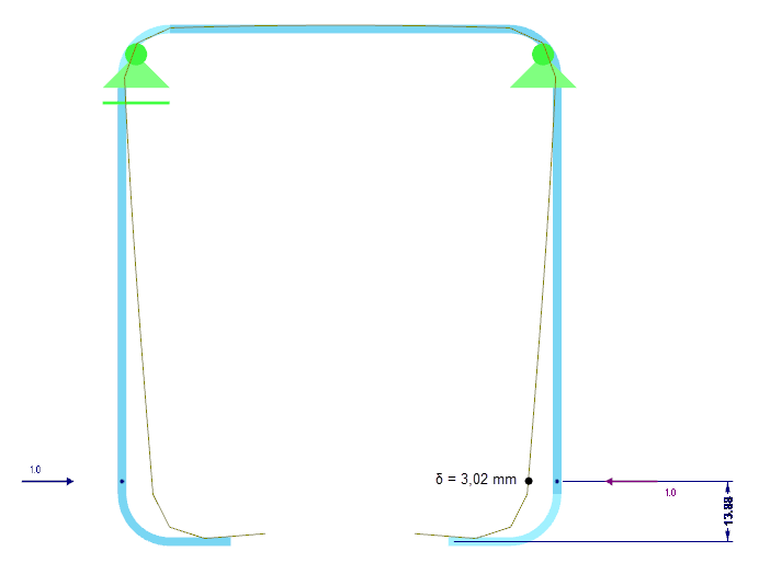
The effective cross-section values of the edge stiffening are calculated with SHAPE-THIN. The edge stiffness is shown in Figure 04.
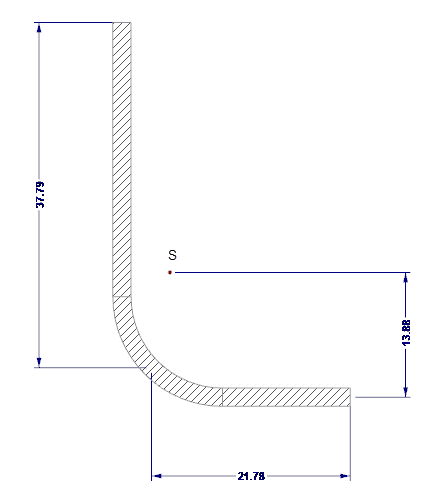
As = 122.58 mm2
Is = 7,130 mm4
zs = 13.88 mm
The spring stiffness K of the edge stiffness is determined on the basis of a structural analysis for the entire cross-section. For this purpose, a unit distance load u, acting in the centroid of the effective stiffener, is applied to the cross-section, and the corresponding deformation δ of the stiffener is calculated. For a rectangular cross-section w/h = t/t = 2/2 mm, the deformation results in δ = 3.02 mm (Figure 05).
The spring stiffness per unit length K can be calculated according to [1], Eq. 5.9 as follows:
According to [1], Eq. 5.15, the critical stress of the edge stiffness results in:
According to [1], Eq. 5.12d, the related slenderness ratio results in:
According to [1], 5.5.3.1 (7), the reduction coefficient for the shape instability is calculated as follows:
According to [1], Eq. 5.17, the reduced effective cross-sectional area of the edge stiffness is obtained, taking into account the flexural buckling:
Effective cross-section properties under pure compression:
The cross-section can be optimized by means of an iterative calculation. For two iterations, it results in the following effective cross-section values:
Area Aeff = 4.62 cm²
Centroidal distance from web zs,eff = 42.18 mm
Centroidal displacement eN,y = zs – zs,eff = 8.78 mm
Determining the Effective Cross-Section Under Pure Bending Stress
Web:
The web is subjected to tension and is thus fully effective.
Flange with edge stiffener:
In the first step, the first approach for the effective cross-section of the stiffener is determined with the assumption that the edge stiffness acts as a rigid support and that σcom,Ed = fyb / γM0.
Flange:
According to [2], Table 4.1, the buckling value results in:
According to [2], 4.4 (2), the buckling slenderness results in:
The slenderness ratio is smaller than the limit value 0.856 according to [2], 4.4(2). Thus, no reduction is required.
According to [2], Table 4.1, the effective widths result in:
Edge stiffness:
According to [1], 5.5.3.2 (5), the buckling value results in:
According to [2], 4.4 (2), the buckling slenderness results in:
The slenderness ratio is smaller than the limit value 0.748 according to [1], 4.4 (2). Thus, no reduction is necessary, that is: ρ = 1.0.
According to [1], Eq. 5.13a, the first approach of the effective width results in:
In the second step, the reduction factor for the shape instability of the cross-section is determined by using the effective first approach for the cross-section, taking into account the elastic translation spring.
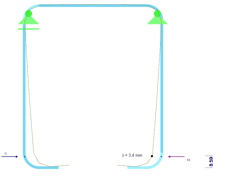
The effective cross-section values of the edge stiffening are calculated with SHAPE-THIN. The edge stiffness is shown in Figure 06.
As = 97.92 mm2
Is = 6,271 mm4
zs = 8.59 mm
The spring stiffness K of the edge stiffness is determined on the basis of a structural analysis for the entire cross-section. For this purpose, a unit distance load u, acting in the centroid of the effective stiffener, is applied to the cross-section and the corresponding deformation δ of the stiffener is calculated. For a rectangular cross-section w/h = t/t = 2/2 mm, the deformation results in δ = 3.4 mm (Figure 07).
The spring stiffness per unit length K can be calculated according to [1], Eq. 5.9 as follows:
According to [1], Eq. 5.15, the critical stress of the edge stiffness results in:
According to [1], Eq. 5.12d, the related slenderness ratio results in:
According to [1], 5.5.3.1 (7), the reduction coefficient for the shape instability is calculated as follows:
According to [1], Eq. 5.17, the reduced effective cross-sectional area of the edge stiffness is obtained taking into account the flexural buckling:
Effective cross-section properties under pure bending stress:
All the cross-section parts are fully effective, so iteration is not necessary.
Area Aeff = 6.86 cm²
Section modulus Weff, y = 17.01 cm³
Cross-Section Design of Combined Loading Due to Compression and Bending
The resistance to pure compression is calculated according to [1], 6.1.3 (1) as follows:
The resistance to pure bending is calculated according to [1], 6.1.4.1 (1) as follows:
The additional moment resulting from the shift of the centroid is determined according to [1], 6.1.9 (2) as follows:
According to [1], 6.1.9 (1), the design for combined loading from compression and bending results in:
The design is thus performed.
Modeling a Cold-Formed C-Section in SHAPE-THIN
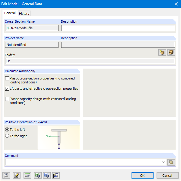
General cold-formed sections can be modeled in SHAPE-THIN. In the general data, activate the "c/t parts and effective cross-section properties" check box (Figure 08).
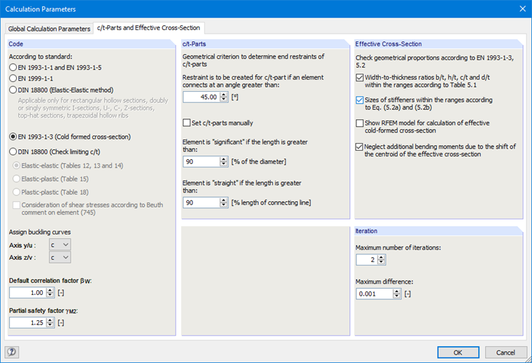
Then, select the "EN 1993-1-3 (Cold-formed cross-section)" option in the "c/t-parts and effective cross-section" tab (Figure 09) of the Calculation Parameters dialog box.
The effective cross-section must be determined separately for pure compression and pure bending. Therefore, select the "Neglect additional bending moments due to the shift of the centroid of the effective cross-section" check box.
We have calculated with two iterations in the example, so two iterations are also set in SHAPE-THIN.
The geometric conditions mentioned in [2], 5.2 for the applicability of the standard can be optionally checked. To do this, select the corresponding check boxes.
The elements of the cross-section have to be entered first. The notional flat widths are usually generated automatically from the geometry conditions, but can also be created as user-defined in Table "1.7 Notional Flat Widths According to EN 1993-1-3" (Figure 10) or in the corresponding dialog box.
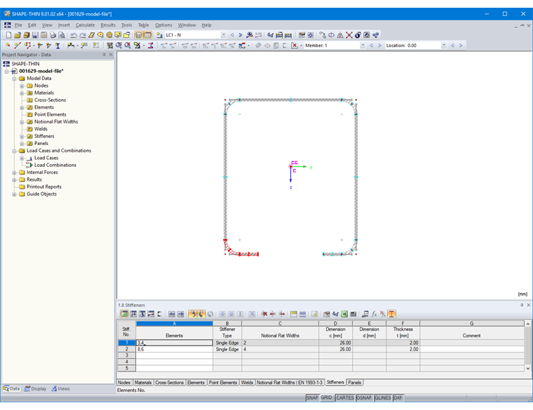
The stiffeners can then be defined in Table "1.8 Stiffeners" or in the corresponding dialog box (Figure 11).
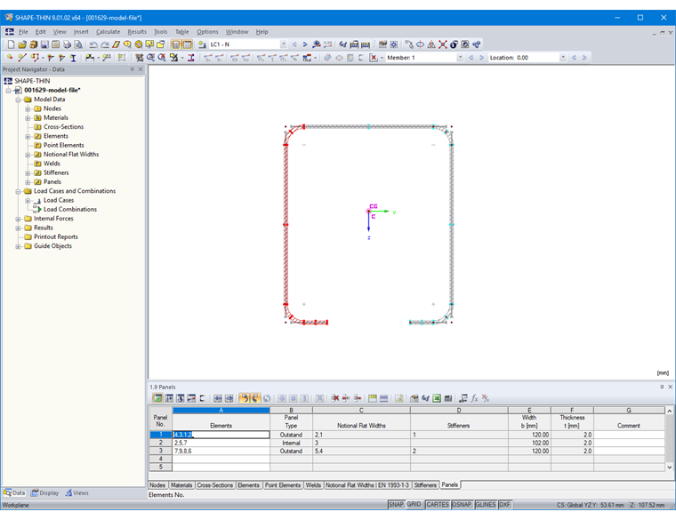
Furthermore, the buckling panel must be specified in Table "1.9 Panels" (Figure 12) or in the corresponding dialog box. To do this, select the elements of the buckling panel. The stiffeners located in the stiffened panel are identified automatically.
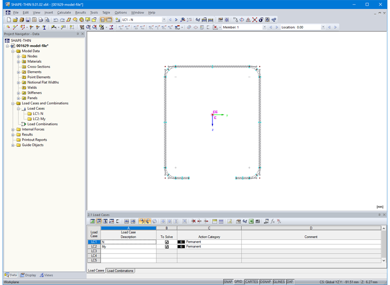
Additionally, a load case for compression force and bending is created in Table "2.1 Load Cases" (Figure 13).
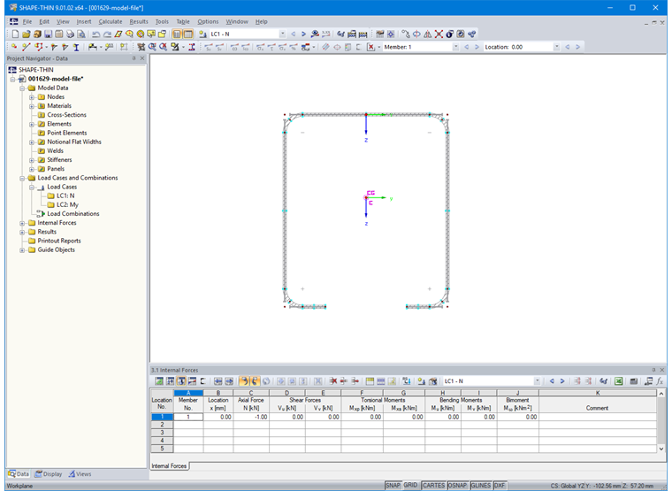
Then, enter the internal forces in Table "3.1 Internal Forces" or in the corresponding dialog box (Figure 14).
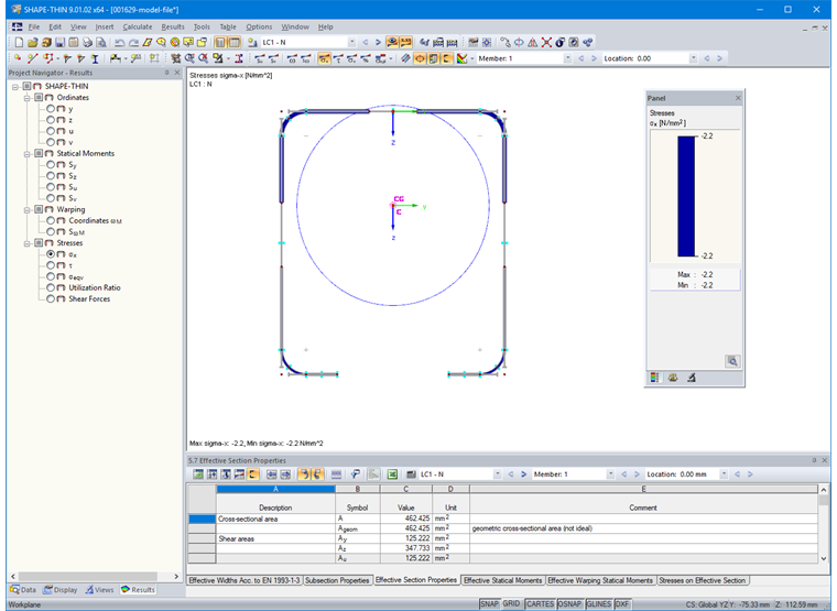
The results of the effective cross-section are available with the "Effective Parts" button (Figure 15).
Cross-Section Design of Cold-Formed C-Section in RF-/STEEL Cold-Formed Sections
Cold-formed sections can be designed according to [1] and [2] with the RF-/STEEL Cold-Formed Sections add-on module.
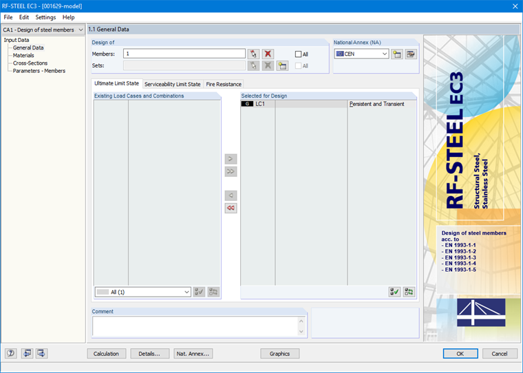
In the General Data, you must first select the member and load case to be designed. "CEN" is selected as the National Annex (Figure 16).
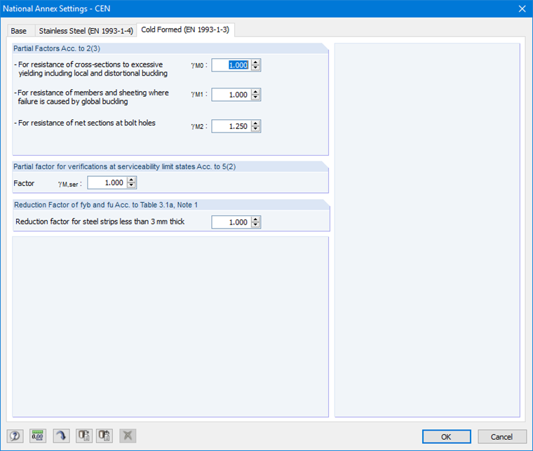
You can see and, if necessary, adjust the parameters of the National Annex in the "Cold-Formed (EN 1993-1-3)" tab of the corresponding window (Figure 17).
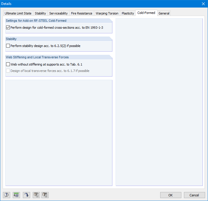
In the Detail settings, activate the design check for cold-formed sections in the "Cold-Formed" tab (Figure 18).
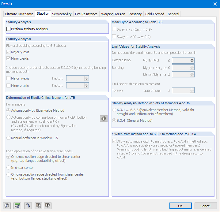
Only the cross-section design should be performed. Therefore, the "Perform stability analysis" check box in the "Stability" tab of the detail settings must be deactivated (Figure 19).
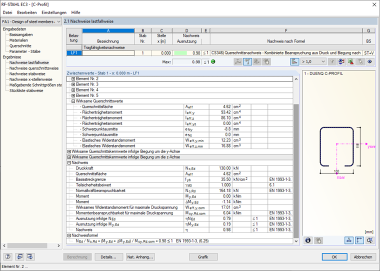
After the calculation, the corresponding output tables show, among other things, effective cross-section properties due to axial force N, bending moment My, bending moment Mz, internal forces, and the entire design (Figure 20).
.png?mw=760&hash=d7c630739737ab9c4e570c2724be0a06b06d01ef)


.png?mw=600&hash=49b6a289915d28aa461360f7308b092631b1446e)


