Introduction
Three-dimensional virtual building models are very impressive. If everything in renderings can be displayed realistically down to the last detail, so that it is almost impossible to distinguish the digital twin from the real model at first glance, a structural analysis should not be a problem. However, what your eyes see is only part of the information that is required for the structural design. You cannot easily see mechanical material properties, hinges, loads, load cases, or resistances in the building model. This requires further accumulation of information and the interpretation skills of engineers who can convert the visible model into an idealized and mechanically equivalent model. A BIM model is more than, for example, a 3D solid model of a building; therefore, it is an ideal introduction to the structural dimensioning of structures. Which paths can be used here?
Relevant Objects in BIM Models for Structural Design
For the structural design, only certain load-bearing parts such as walls, columns, ceilings, and beams are relevant. First of all, you have to select the components that are of interest for the structural analysis in the BIM model. This is also referred to as the structural model. Normally, modern BIM software allows you to highlight these parts specifically. When exchanging data, only this submodel that has been marked as load-bearing is used for structural design. Examples of irrelevant parts include windows, doors, and installations such as electrical equipment and water pipes.
The submodel that is created for the structural calculation must then generally be edited further. Unconnected columns and beams must either be shifted or connected by means of coupling elements. Similarly, you have to connect ceilings and walls if their effective lines do not meet in an edge. If necessary, you have to decide if an entire model or a submodel has to be calculated. For example, in the case of a hall, it may be sufficient to calculate a frame that is implemented identically several times. The same applies to ceilings in multi-story buildings.
Types of Interfaces
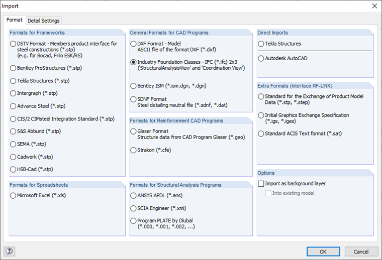
If you want to transfer models from software to software, these questions arise: to which data format do you want to transfer, and do you want to use direct interfaces?
Open Interfaces
If you use open standards (openBIM), the IFC format is the be-all and end-all. The advantage of open standards is that, ideally, every software company utilizing this standard can exchange data directly with all other software companies that also utilize this standard. However, the quality of the data exchange depends on how well the respective converters for reading and writing IFC are implemented, and how the IFC data can be converted into the native data of the respective program. In most cases, the IFC models are only referenced in the other software. The program always uses either data based on IFC 2x3 Coordination View 2.0, or the newer version of IFC 4 Reference View 1.2. This means you can visualize the data and obtain information. Likewise, these models are suitable for collision checks. To continue working with the model, however, you have to convert the IFC models to the native data format of the software used. Structural Analysis View is of interest to structural analysis programs. This view is used for exchanging structural models and includes the description of analysis models with structural data such as supports, hinges, load cases, and loads. When exchanging data via IFC, it is, therefore, very important that you know which view contains the corresponding IFC file.
.png?mw=760&hash=c88f3514b006260a73e08b756778d026e656891d)
Direct Interfaces
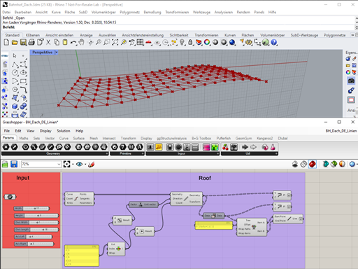
If two software solutions are directly coupled, the path via the IFC format or another data format is unnecessary. No transfer file is created. The information is read directly from application A by means of the necessary APIs (Application Programming Interfaces, programmable interfaces) and native objects are then created immediately in application B. Since there is a risk of losing data with every data exchange, direct coupling has certain advantages because the two conversion steps of writing and reading the IFC file are no longer necessary. Only one conversion process, directly from software A to B, is necessary. Additionally, missing definition structures do not play a role in IFC format for direct couplings, and you do not have to worry how special objects can be described in the IFC format. The disadvantage of direct coupling is that it has to be programmed individually for each program pair, and providers cannot be switched easily. In the meantime, however, projects have also been realized in which engineering offices have written program interfaces that are tailored exactly to their own processes. The prerequisite for this is that the program pairs provide the APIs, and program documentation is available. These types of adapted interfaces offer a considerably higher degree of automation of the planning process at a manageable expense, and thus an enormous potential for saving time and costs, and avoiding errors. It is also possible to construct depending on parameters, especially in the design phase.
Synchronizing Changes
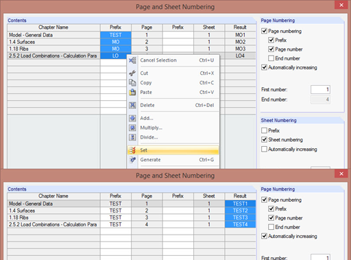
Structural calculations are required in the design phase (performance phases 1 to 3) in order to optimize the design of the structural system and to specify section sizes. Usually, several drafts are considered and the architectural draft and structural design are coordinated with each other. Based on the structural design in the BIM software (architect, structural system), the structural components are transferred to the structural analysis software (RFEM, RSTAB) as a complete model or a partial model and calculated there. Possible changes from the structural analysis can affect the stiffening concept or cross-sections. The current state of the art is that changes can be exchanged digitally. For example, with the direct interface between RFEM and Autodesk Revit or Tekla Structures, it is possible to update section changes or add new structural components to the design model. Recent developments also make it possible to transfer reinforcement designs digitally (RF-CONCRETE add-on module) in the form of actual reinforcement (members and meshes). This creates ideal conditions for quantity determination and further detailed planning.
.png?mw=760&hash=5f9767ea5982b631a721cef51ab36f9971a2bd3a)
Merging Data from Structural Analysis and BIM Models
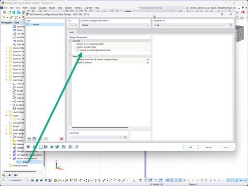
BIM stands for interdisciplinary coordination throughout all work phases. To assess feasibility at an early stage, or for further processing of results in other companies or other service providers, it may be helpful to display or make available structural results in the BIM model (deformations, internal forces). In addition, it is possible to combine the specific strengths of BIM software in planning with those of typical structural analysis software. It is thus possible to display items of a structural model in the BIM model or, depending on the application, directly generate reinforcement drawings based on the structural model. It is also possible to directly transfer the design results from the FEA program RFEM to Revit as 3D reinforcement.
Stay up to Date and Test it Yourself
By promoting digital planning methods, software companies are constantly offering new solutions and improvements. Therefore, it is important to get informed and to know the possible workflows. You can find all the important information about BIM from Dlubal Software at www.dlubal.com/BIM, offering technical articles, webinars, videos, and so on.


.png?mw=512&hash=a2d64046b1b82d01d353d39d4a145023e6992bce)
.png?mw=350&hash=b2016692685990cc8253a1c385015be3aa92d93b)

.png?mw=350&hash=185ea38ae8cf0dc594f8cadf29ff051c99033ece)


.jpg?mw=350&hash=0699344bce74030cffe080ac61d2fafe33a8c178)
.jpg?mw=350&hash=9689cb7a943dc7836a932b35bfde4a01caf8bb13)


.png?mw=600&hash=49b6a289915d28aa461360f7308b092631b1446e)


