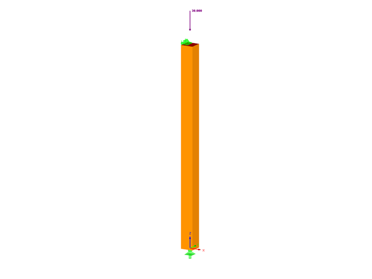
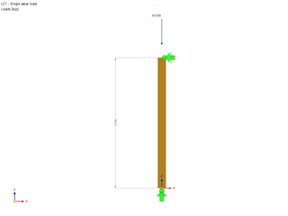
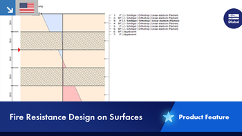
A 10-foot-long, nominal 8 inch ⋅ 8 inch Alaska Cedar Select Structural column with an axial load of 30.00 kips will be designed. The goal of this analysis is to determine the adjusted compression factors and adjusted compressive design value of the column. A normal load duration and pinned supports at each end of the member are assumed. The loading criteria are simplified for this example. Normal loading criteria can be referenced in Sec. 1.4.4 [1]. In Figure 01 a diagram of the simple column with loads and dimensions is shown.

Column Properties
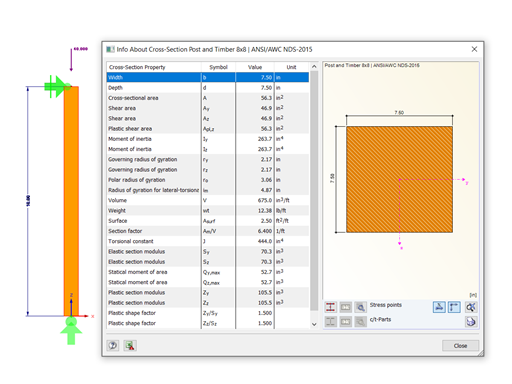
The cross-section used in this example is an 8 inch ⋅ 8 inch post and timber. The actual cross-section property calculations of the timber column can be viewed below:
b = 7.50 in, d = 7.50 in, L = 10.00 ft
Gross cross-section area:
Ag = b ⋅ d = 7.50 in ⋅ 7.50 in = 56.25 in²
Section modulus:
Moment of inertia:
The material that will be used for this example is Alaska Cedar, 5"x5" and Larger, Beam and Stringer, Select Structural. The material properties are as follows:
Reference compression design value:
Fc = 925 psi
Minimum modulus of elasticity:
Emin = 440 ksi
Column Adjustment Factors
For the design of timber members as per the 2018 NDS standard and the ASD method, stability factors (or adjustment factors) must be applied to the compressive design value (fc). This will ultimately provide the adjusted compressive design value (F'c). The factor F'c is determined with the following equation, highly dependent on the listed adjustment factors from Table 4.3.1 [1]:
F'c = Fc ⋅ CD ⋅ CM ⋅ Ct ⋅ CF ⋅ Ci ⋅ CP
Below, each adjustment factor is determined:
CD - The load duration factor is implemented to take into account different periods of loading. Snow, wind, and earthquakes are taken into account with CD. This factor must be multiplied by all reference design values except for the modulus of elasticity (E), modulus of elasticity for beam and column stability (Emin), and the compression forces perpendicular to the grain (Fc) based on Sec. 4.3.2 [1]. CD in this case is set to 1.00 as per Sec. 2.3.2 [1] assuming a normal load duration of 10 years.
CM - The wet service factor references design values for structural sawn lumber based on moisture service conditions specified in Sec. 4.1.4 [1]. In this case, based on Sec. 4.3.3 [1], CM is set to 0.910.
Ct - The temperature factor is controlled by a member's sustained exposure to elevated temperatures up to 150 degrees Fahrenheit. All reference design values will be multiplied by Ct. Utilizing Table 2.3.3 [1], Ct is set to 1.00 for all reference design values, assuming temperatures are equal to or lesser than 100 degrees Fahrenheit.
CF - The size factor for sawn lumber does not consider wood as a homogeneous material. The size of the column and type of wood are taken into account. For this example, our column has a depth lesser than or equal to 12 inches. Referencing Table 4D based on the size of the column, a factor of 1.00 is applied. This info can be found in Sec. 4.3.6.2 [1].
Ci - The incising factor considers the preservation treatment applied to the wood to resist decay and avoid fungal growth. Most of the time this involves pressure treatment, but in some cases requires the wood to be incised increasing the surface area for chemical coverage. For this example, we will be assuming the wood is incised. Referencing Table 4.3.8 [1], an overview of the factors by which each member property must be multiplied is shown.
Adjusted Modulus of Elasticity
The reference modulus of elasticity values (E and Emin) must also be adjusted. The adjusted modulus of elasticity (E' and E'min) are determined from Table 4.3.1 [1] and the incising factor Ci is equal to 0.95 from Table 4.3.8 [1].
E' = E ⋅ CM ⋅ Ct ⋅ Ci = 1,140,000.00 psi
E'min = Emin ⋅ CM ⋅ Ct ⋅ Ci = 418,000.00 psi
Column Stability Factor (CP)
The column stability factor (CP) is needed in order to calculate the column's adjusted compressive design value and the compressive design ratio. The following steps will include the necessary equations and values to find CP.
The equation used to calculate Cp is Eqn. (3.7-1) referenced in Section 3.7.1.5. The reference compression design value parallel to grain (Fc) is required and calculated below:
F'c = Fc ⋅ CD ⋅ CM ⋅ Ct ⋅ CF ⋅ Ci = 673.40 psi
The next value that needs to be calculated in Eqn. (3.7-1) is the critical buckling design value for compression members (FcE).
The slenderness ratio is calculated as so:
The slenderness ratio is applied to the equation for FcE and the following value is calculated:
FcE = 1342.17 psi
The last variable needed is (c), which is equal to 0.8 for sawn lumber. All of the variables can be applied to Eqn. (3.7-1) and the following value is calculated for CP.
Now, all adjustment factors have been determined from Table 4.3.1 [1]. Therefore, the adjusted compressive design value parallel to grain (F'c) can be calculated.
F'c = Fc ⋅ CD ⋅ CM ⋅ Ct ⋅ CF ⋅ Ci ⋅ Cp = 585.86 psi
Column Design Ratio
The ultimate goal of this example is to obtain the design ratio for this simple column. This will determine if the member size is adequate under the given load or if it should be further optimized. Calculating the design ratio requires the adjusted compressive design value parallel to the grain about both axes (F'c) and actual compressive stress parallel to the grain (fc). In this case, the cross-section is symmetrical, so F'c is equivalent for both the x- and the y-axis.
The actual compressive stress (fc) is calculated below:
The adjusted compressive design value parallel to the grain (F'c) and the actual compressive stress (fc) are used to compile the design ratio (η) as per Sec. 3.6.3.
Application in RFEM
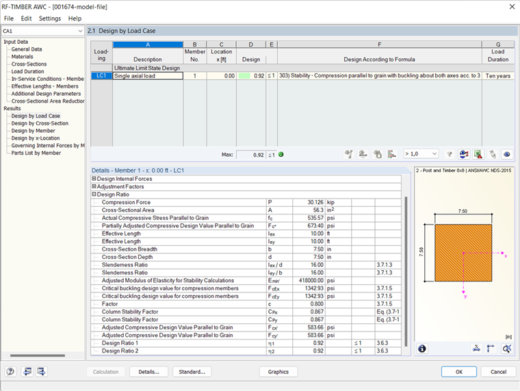
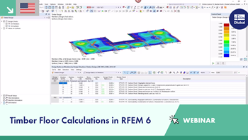
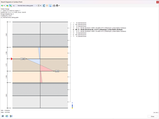
For timber design as per the 2018 NDS standard in RFEM, the add-on module RF-TIMBER AWC analyzes and optimizes cross-sections based on loading criteria and member capacity for a single member or a set of members. This is available for either LRFD or ASD design methods. When modeling and designing the column example above in RF-TIMBER AWC, the results can be compared.
In the General Data table of the RF-TIMBER AWC add-on module, the member, loading conditions, and design methods are selected. The material and cross-sections are defined from RFEM and the load duration is set to ten years. The moisture service condition is set as Wet and the temperature is equal to or below 100 degrees Fahrenheit. Lateral-Torsional Buckling is defined according to Table 3.3.3 [1]. The module calculations produce an actual compressive stress parallel to the grain (fc) of 535.57 psi and an adjusted compressive design value parallel to the grain (F'c) of 583.66 psi. A design ratio (η) of 0.92 is determined from these values aligning well with the analytical hand calculations shown above.


.png?mw=512&hash=4e74affa9ad0c7b703151c5085ac9b8e59171c23)


.jpg?mw=350&hash=8f312d6c75a747d88bf9d0f5b1038595900b96c1)


.png?mw=600&hash=49b6a289915d28aa461360f7308b092631b1446e)