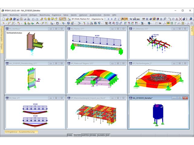
The structural analysis software RFEM 6 is the basis of a modular software system. The main program RFEM 6 is used to define structures, materials, and loads of planar and spatial structural systems consisting of plates, walls, shells, and members. The program also allows you to create combined structures as well as to model solid and contact elements.
RSTAB 9 is a powerful analysis and design software for 3D beam, frame, or truss structure calculations, reflecting the current state of the art and helping structural engineers meet requirements in modern civil engineering.
Do you often spend too long calculating cross-sections? Dlubal Software and the RSECTION stand-alone program facilitate your work by determining section properties of various cross-sections and performing a subsequent stress analysis.
Do you always know where the wind is blowing from? From the direction of innovation, of course! With RWIND 2, you have a program at your side that uses a digital wind tunnel for the numerical simulation of wind flows. The program simulates these flows around any building geometry and determines the wind loads on the surfaces.
Are you looking for an overview of snow load zones, wind zones, and seismic zones? Then you are in the right place. Use the Geo-Zone Tool to determine quickly and efficiently snow loads, wind speeds, and seismic data according to ASCE 7‑16 and other international standards.
Would you like to try out the capabilities of the Dlubal Software programs? You have the opportunity to do so! The free 90-day full version allows you to thoroughly test all our programs.
For the CSA O86 and NDS, the Modification and Adjustment factors used in the Timber Design add-on in RFEM 6 can be manually adjusted. The factors are listed under the material properties.
To edit them manually, first open the material(s) being used for timber design and then set them to "User-Defined". Once this is done, navigate to the Timber Design tab where the Modification and Adjustment factors can be entered manually.
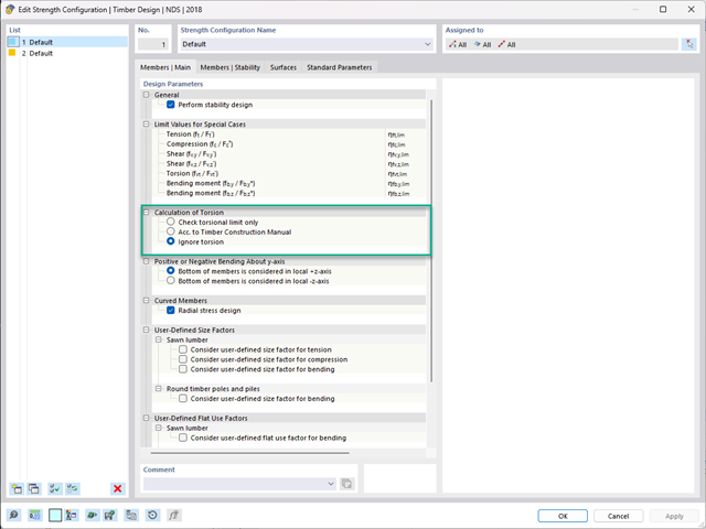
The Calculation for Torsion in the NDS Strength Configuration works together with the torsion limit set to ensure the safety of the member and structure. Below, you find a short explanation for each option:
Check torsional limit only:The ratio torsion check is compared to the torsion limit. If the ratio is smaller than the limit, then no further calculation is carried out. If the ratio is bigger than the torsion limit, an error will be shown in the design check. The error is then the most governing design check in the graphical and tabular results.
According to Timber Construction Manual:Torsion design is according to the Timber Construction Manual 4.6, and the result is a typical design ratio based on the calculation.
Ignore torsion:This setting is very similar to the first option. The ratio is compared from the torsion calculation to the torsion limit. If the ratio is smaller than the limit, then no further calculation is carried out. If the ratio is bigger than the limit, then a warning is shown in the design check. This warning will not be a governing design check in the results tables or graphics and serves only as a warning for safety considerations.
To neglect all torsion for the member design check, the limit value for torsion must be increased.
Yes, the data are freely accessible. You can download the presentations and finished models by the speakers under Downloads below.
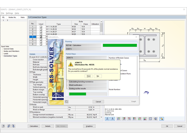
Originally, the typified moment-resistant connections of the DSTV guidelines were not designed to be subjected to normal force. However, a load of up to 5% of the plastic normal force resistance of the connected beam may be neglected according to the instructions given in the guideline. If the beam contains a higher normal force, a warning message is also given in RF‑/JOINTS Steel - DSTV.
With the additional volume of the 2018 guideline, additional moment-resistant connections of the IM designation were added. In the beam-to-beam connection type, they are also designed to resist the normal forces. If you design such a connection, the normal force resistance design including the MN interaction appears instead of the warning message.
For beam-column connections, the normal force resistance of column components is not included in the table values according to the DSTV guideline. Therefore, the connection must be designed separately again. Consequently, the warning message appears anyway. As an alternative, you can use RF‑/JOINTS Steel - Rigid.
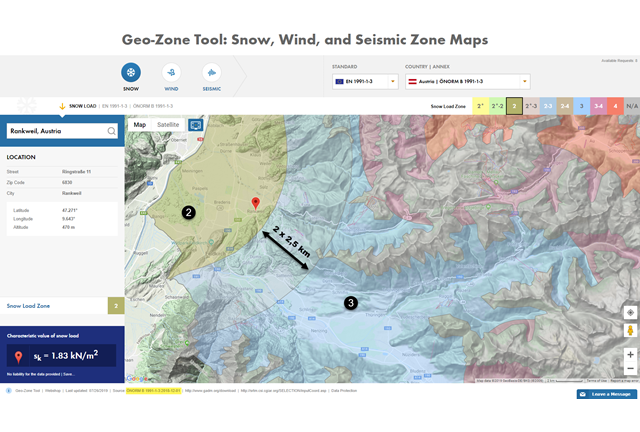
With National Annex ÖNORM B 1991‑1‑3:2018‑12, Austria has textually redrafted the width of tolerance zones.
[1] In the third paragraph under "Annex B", the standard states accordingly that within 2.5 km on both sides of the zone boundary, the characteristic value sk is the average of the affected zones. In the area of Vienna, we can assume 250 m per side. This results in the tolerance zone width of 2 x 2.5 km = 5 km in the country and 2 x 250 m = 500 m in Vienna.
→ See Snow Load Map of Austria
This regulation was applied with the update of ÖNORM B 1991‑1‑3: 2018̩12 on our website Snow Load, Wind Speed, and Seismic Load Maps.
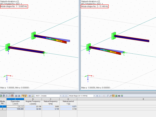
Yes, all supports with a spring constant are considered in the RF‑/DYNAM Pro add-on module. In detail, this means that the elastic supports are considered in the following areas:
The attached example clearly shows how the mode shapes of a member change when an elastic nodal support is added.