
In the Geotechnical Analysis add-on, the Hoek-Brown material model is available. The model shows linear-elastic ideal-plastic material behavior. Its nonlinear strength criterion is the most common failure criterion for stone and rocks.
You can enter the material parameters using
- Rock parameters directly, or alternatively via
- GSI classification.
Detailed information about this material model and the definition of the input in RFEM can be found in the respective chapter Hoek-Brown Model of the online manual for the Geotechnical Analysis add-on.

In the Steel Joints add-on, you can classify the joint stiffness.
In addition to the initial stiffness, the table also shows the limit values for hinged and rigid connections for the selected internal forces N, My, and/or Mz. The resulting classification is then displayed in tables as "hinged", "semi-rigid", or "rigid".
Go to Explanatory Video
The design checks for the members you have selected are carried out taking into account the governing component temperature. You can perform the cross-section design checks and stability analyses according to EN 1993‑1‑2, Section 4.2.3, in the Steel Design add-on. All reduction factors and coefficients that are necessary are stored accordingly and are taken into account when determining the load-bearing capacity.
The effective lengths for the equivalent member design are taken directly from the strength entries. You don't need to enter them again.
In each design, perform the cross-section classification first. For the cross-sections of Class 4, the design is performed automatically according to EN 1993‑1‑2, Annex E.
- Available for general thin-walled RSECTION cross-sections
- Classification according to
- EN 1993-1-1
- EN 1993-1-4
- EN 1999-1-1
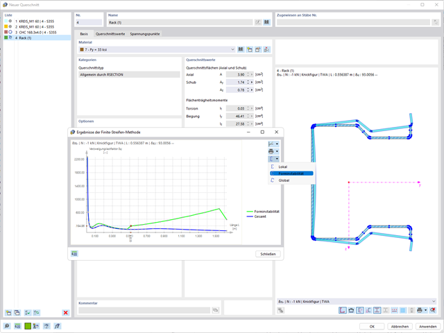
- Determination of the effective section according to
- EN 1993-1-5
- EN 1993-1-3
- EN 1999-1-1
- Consideration of the effects of distortional buckling of cold-formed sections via eigenvalue method
- Determination of the stresses on the effective section and gross section
- Cross-section, stability, and serviceability limit state design checks of RSECTION cross-sections of Class 4 according to EN 1993‑1‑1 or EN 1999‑1‑1 in the Steel Design or Aluminum Design add-ons
- Cross-section checks for cold-formed RSECTION cross-sections according to EN 1993‑1‑3 in the Steel Design add-on
- Available for all National Annexes integrated in the Steel Design add-on
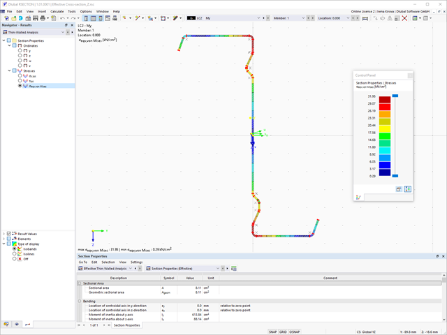
Are you just waiting for your results after the design? The design results are displayed in the usual way in the Steel Design add-on. In the corresponding output tables, you can find the classification, the effective section properties, and the design check, among other things. The stresses are displayed to you graphically on the effective section as well as on the gross section.

- Design of tension, compression, bending, shear, torsion, and combined internal forces
- Tension design with consideration of a reduced section area (for example, hole weakening)
- Automatic classification of cross-sections to check local buckling
- Internal forces from the calculation with Torsional Warping (7 DOF) are taken into account by means of the equivalent stress check (currently not for the design standards AISC 360‑16 and GB 50017).
- Design of cross-sections of Class 4 with effective cross-section properties according to EN 1993‑1‑3 (licenses for RSECTION and Effective Sections are required for the RSECTION cross-sections)
- Shear buckling check according to EN 1993‑1‑5 with consideration of transverse stiffeners
- Design of stainless steel components according to EN 1993‑1‑4

- Design of tension, compression, bending, shear, torsion, and combined internal forces
- Tension design with consideration of a reduced section area (for example, hole weakening)
- Automatic classification of cross-sections to check local buckling
- Internal forces from the calculation with Torsional Warping (7 DOF) are taken into account by means of the equivalent stress check (currently not yet for the design standard ADM 2020).
- Design of cross-sections of Class 4 with effective cross-section properties according to EN 1993‑1‑5 (licenses for RSECTION and Effective Sections are required for the RSECTION cross-sections)
- Shear buckling check with consideration of transverse stiffeners

- Import of materials, cross-sections, and internal forces from RFEM/RSTAB
- Steel design of thin‑walled cross‑sections according to EN 1993‑1‑1:2005 and EN 1993‑1‑5:2006
- Automatic classification of cross-sections according to EN 1993-1-1:2005 + AC:2009, Cl. 5.5.2, and EN 1993-1-5:2006, Cl. 4.4 (cross-section class 4), with optional determination of effective widths according to Annex E for stresses under fy
- Integration of parameters for the following National Annexes:
-
 DIN EN 1993-1-1/NA:2015-08 (Germany)
 -
 ÖNORM B 1993-1-1:2007-02 (Austria)
 -
 NBN EN 1993-1-1/ANB:2010-12 (Belgium)
 -
 BDS EN 1993-1-1/NA:2008 (Bulgaria)
 -
 DS/EN 1993-1-1 DK NA:2015 (Denmark)
 -
 SFS EN 1993-1-1/NA:2005 (Finland)
 -
 NF EN 1993-1-1/NA:2007-05 (France)
 -
 ELOT EN 1993-1-1 (Greece)
 -
 UNI EN 1993-1-1/NA:2008 (Italy)
 -
 LST EN 1993-1-1/NA:2009-04 (Lithuania)
 -
 UNI EN 1993-1-1/NA:2011-02 (Italy)
 -
 MS EN 1993-1-1/NA:2010 (Malaysia)
 -
 NEN EN 1993-1-1/NA:2011-12 (Netherlands)
 - NS EN 1993-1-1/NA:2008-02 (Norway)
-
 PN EN 1993-1-1/NA:2006-06 (Poland)
 -
 NP EN 1993-1-1/NA:2010-03 (Portugal)
 -
 SR EN 1993-1-1/NB:2008-04 (Romania)
 -
 SS EN 1993-1-1/NA:2011-04 (Sweden)
 -
 SS EN 1993-1-1/NA:2010 (Singapore)
 -
 STN EN 1993-1-1/NA:2007-12 (Slovakia)
 -
 SIST EN 1993-1-1/A101:2006-03 (Slovenia)
 -
 UNE EN 1993-1-1/NA:2013-02 (Spain)
 -
 CSN EN 1993-1-1/NA:2007-05 (Czech Republic)
 -
 BS EN 1993-1-1/NA:2008-12 (the United Kingdom)
 -
 CYS EN 1993-1-1/NA:2009-03 (Cyprus)
 - In addition to the National Annexes (NA) listed above, you can also define a specific NA, applying user‑defined limit values and parameters.
- Automatic calculation of all required factors for the design value of flexural buckling resistance Nb,Rd
- Automatic determination of the ideal elastic critical moment Mcr for each member or set of members on every x-location according to the Eigenvalue Method or by comparing moment diagrams. You only have to define the lateral intermediate supports.
- Design of tapered members, unsymmetric sections or sets of members according to the General Method as described in EN 1993-1-1, Cl. 6.3.4
- In the case of the General Method according to Cl. 6.3.4, optional application of "European lateral-torsional buckling curve" according to Naumes, Strohmann, Ungermann, Sedlacek (Stahlbau 77 [2008], pp. 748‑761)
- Rotational restraints can be taken into account (trapezoidal sheeting and purlins)
- Optional consideration of shear panels (for example, trapezoidal sheeting and bracing)
- RF-/STEEL Warping Torsion module extension (license required) for stability analysis according to the second-order analysis as stress analysis including consideration of the 7th degree of freedom (warping)
- Module extension RF-/STEEL Plasticity (license required) for plastic analysis of cross‑sections according to Partial Internal Forces Method (PIFM) and Simplex Method for general cross‑sections (in connection with the RF‑/STEEL Warping Torsion module extension, it is possible to perform the plastic design according to the second‑order analysis)
- Module extension RF-/STEEL Cold-Formed Sections (license required) for ultimate and serviceability limit state designs for cold-formed steel members according to the EN 1993-1-3 and EN 1993-1-5 standards
- ULS design: Selection of fundamental or accidental design situations for each load case, load combination, or result combination
- SLS design: Selection of characteristic, frequent, or quasi-permanent design situations for each load case, load combination, or result combination
- Tension analysis with definable net cross-section areas for member start and end
- Weld designs of welded cross-sections
- Optional calculation of warp spring for nodal support on sets of members
- Graphic of design ratios on cross-section and in RFEM/RSTAB model
- Determination of governing internal forces
- Filter options for graphical results in RFEM/RSTAB
- Representation of design ratios and cross‑section classes in the rendered view
- Color scales in result windows
- Automatic cross-section optimization
- Transfer of optimized cross-sections to RFEM/RSTAB
- Parts lists and quantity surveying
- Direct data export to MS Excel
- Verifiable printout report
- Possibility to include the temperature curve in the report
- Design of members and sets of members for tension, compression, bending, shear, combined internal forces, and torsion
- Stability analysis of buckling and lateral-torsional buckling
- Automatic determination of critical buckling loads and critical buckling moments for general load applications and support conditions by means of a special FEA program (eigenvalue analysis) integrated in the module
- Alternative analytical calculation of the critical buckling moment for standard situations
- Optional application of discrete lateral supports to beams and continuous members
- Automatic cross-section classification (compact, noncompact, and slender)
- Serviceability limit state design (deflection)
- Cross-section optimization
- A wide range of available cross-sections, such as rolled I-sections; channel sections; T-sections; angles; rectangular and circular hollow sections; round bars; symmetrical and asymmetrical, parametric I-, T-, and angle sections; double angles
- Clearly arranged input and result windows
- Detailed result documentation including references to design equations of the used standard
- Various filter and sorting options of results, including result lists by member, cross-sections, and x-location, or by load case, load combination, and result combination
- Result table of member slenderness and governing internal forces
- Parts list with weight and solid specifications
- Seamless integration in RFEM/RSTAB
- Metric and imperial units

- Modeling of the cross-section via elements, sections, arcs, and point elements
- Expansible library of material properties, yield strengths, and limit stresses
- Section properties of open, closed, or non-connected cross-sections
- Ideal section properties of cross-sections consisting of different materials
- Determination of weld stresses in fillet welds
- Stress analysis including design of primary and secondary torsion
- Check of c/t-ratios
- Effective cross-sections according to
- EN 1993-1-5 (including stiffened buckling panels according to Section 4.5)
-
 EN 1993-1-3
 -
EN 1999-1-1
-
to DIN 18800-2
- Classification according to
-
EN 1993-1-1
-
EN 1999-1-1
-
- Interface with MS Excel to import and export tables
- Printout report

SHAPE-THIN calculates all relevant cross‑section properties, including plastic limit internal forces. Overlapping areas are set close to reality. If cross-sections consist of different materials, SHAPE‑THIN determines the effective cross‑section properties with respect to the reference material.
In addition to the elastic stress analysis, you can perform the plastic design including interaction of internal forces for any cross‑section shape. The plastic interaction design is carried out according to the Simplex Method. You can select the yield hypothesis according to Tresca or von Mises.
SHAPE-THIN performs a cross-section classification according to EN 1993-1-1 and EN 1999-1-1. For steel cross-sections of cross-section class 4, the program determines effective widths for unstiffened or stiffened buckling panels according to EN 1993-1-1 and EN 1993-1-5. For aluminum cross-sections of cross-section class 4, the program calculates effective thicknesses according to EN 1999-1-1.
Optionally, SHAPE‑THIN checks the limit c/t-values in compliance with the design methods el‑el, el‑pl, or pl‑pl according to DIN 18800. The c/t-zones of elements connected in the same direction are recognized automatically.
- Design of tension, compression, bending, shear, and combined internal forces
- Stability analysis for flexural buckling and lateral-torsional buckling
- Automatic determination of critical buckling loads and critical buckling moments for general load applications and support conditions by means of a special FEA program (eigenvalue analysis) integrated in the module
- Optional application of discrete lateral supports to beams
- Automatic cross-section classification
- Deformation analysis (serviceability)
- Cross-section optimization
- Wide range of cross-sections available, such as rolled I-sections, C-sections, rectangular hollow sections, angles, double angles (arrangement flange on flange), T-sections. Welded sections: I-shaped (symmetrical and asymmetrical about major axis), channel sections (symmetrical about major axis), rectangular hollow sections (symmetrical and asymmetrical about major axis), angles, round pipes, and round bars
- Clearly arranged result tables
- Detailed result documentation including references to design equations of the used standard
- Various filter and sorting options of results, including result lists by member, cross-sections, x-location, or by load case, load and result combination
- Result table of member slenderness and governing internal forces
- Parts list with weight and solid specifications
- Seamless integration in RFEM/RSTAB
- Metric and imperial units
- Design of tension, compression, bending, shear, and combined internal forces
- Stability analysis for flexural buckling and lateral-torsional buckling
- Automatic determination of critical buckling loads and critical buckling moments for general load applications and support conditions by means of a special FEA program (eigenvalue analysis) integrated in the module
- Optional application of discrete lateral supports to beams
- Automatic cross-section classification (Class 1 to 3)
- Deformation analysis (serviceability)
- Cross-section optimization
- Wide range of cross-sections available, such as rolled I-sections, C-sections, rectangular hollow sections, angles, double angles (arrangement flange on flange), T-sections. Welded sections: I-shaped (symmetrical and asymmetrical about major axis), channel sections (symmetrical about major axis), rectangular hollow sections (symmetrical and asymmetrical about major axis), angles, round pipes, and round bars
- Clearly arranged result tables
- Detailed result documentation including references to design equations of the used standard
- Various filter and sorting options of results, including result lists by member, cross-sections, x-location, or by load case, load and result combination
- Result table of member slenderness and governing internal forces
- Parts list with weight and solid specifications
- Seamless integration in RFEM/RSTAB
- Metric and imperial units
- Design of members and sets of members for compression, bending, shear, and combined actions
- Stability analysis of buckling and lateral-torsional buckling
- Automatic determination of critical buckling loads and critical buckling moments for general load applications and support conditions by means of a special FEA program (eigenvalue analysis) integrated in the module
- Optional application of discrete lateral supports to beams
- Automatic cross-section classification (Class 1 to 4)
- Deformation analysis (serviceability)
- Cross-section optimization
- A wide range of available cross-sections, such as rolled I-sections; channel sections; T-sections; angles; rectangular and circular hollow sections; round bars; symmetrical and asymmetrical, parametric I-, T-, and angle sections; double angles
- Optional import of buckling lengths from RF-STABILITY/RSBUCK
- Detailed result documentation including references to design equations of the used standard
- Various filter and sorting options of results including result lists by member, cross-section, x-location, or by load cases, load and result combinations
- Result table of member slenderness and governing internal forces
- Parts list with weight and solid specifications
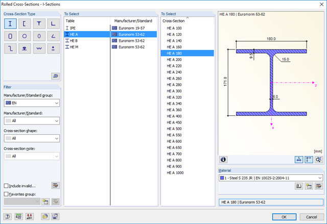
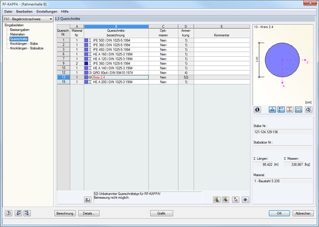
RF-/STEEL EC3 automatically imports the cross-sections defined in RFEM/RSTAB. It is possible to design all thin-walled cross-sections. The program automatically selects the most efficient method according to standards.
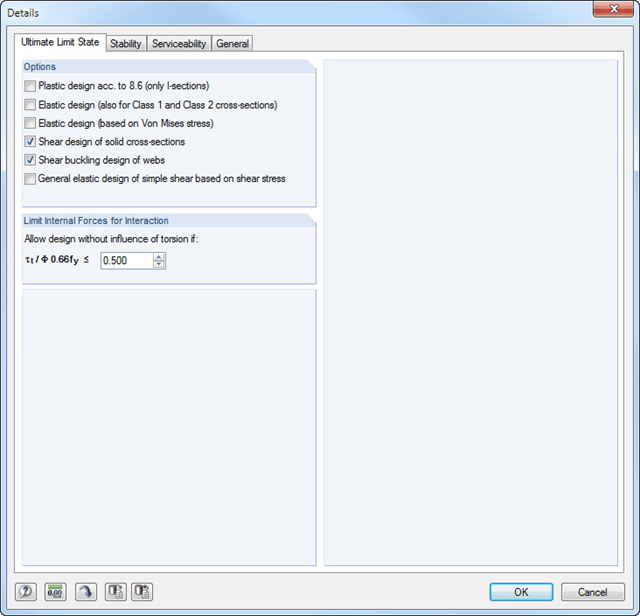
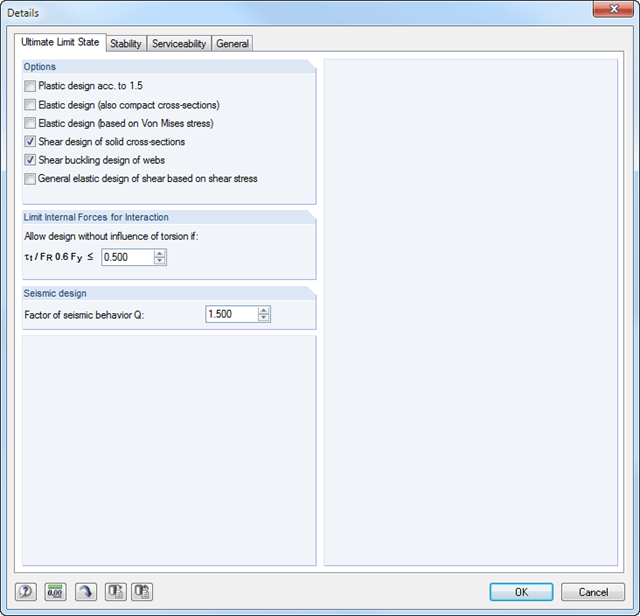
The ultimate limit state design takes into account several loads and you can select the interaction designs available in the standard.
The classification of designed cross-sections into Classes 1 to 4 is an essential part of the analysis according to Eurocode 3. This way, you can check the limitation of the design and rotational capacity by means of the local buckling of cross-section parts. RF-/STEEL EC3 determines the c/t-ratios of the cross-section parts subjected to compression stress and performs the classification automatically.
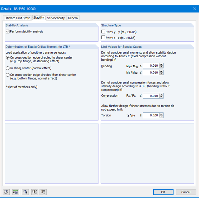
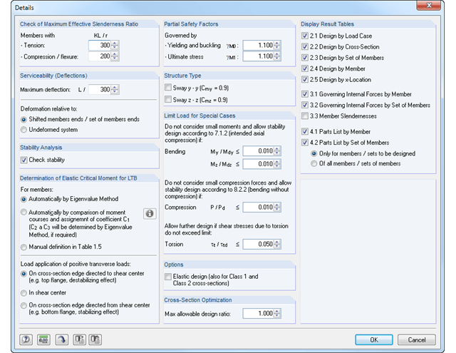
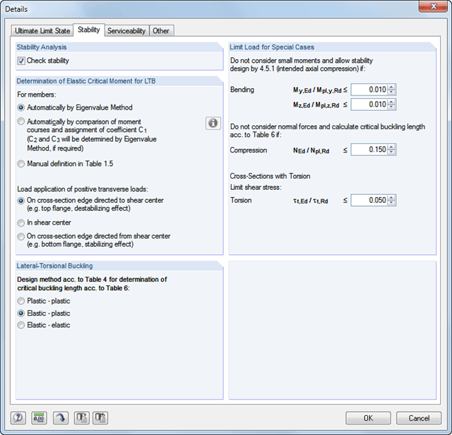
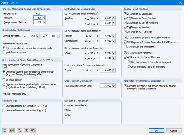
For the stability analysis, you can specify for each member or set of members whether flexural buckling occurs in the y- and/or the z-direction. You can also define additional lateral restraints in order to represent the model close to reality. The slenderness ratio and elastic critical load are determined automatically on the basis of the boundary conditions of RF-/STEEL EC3. The elastic critical moment for lateral-torsional buckling required for the lateral-torsional buckling analysis can be determined automatically or specified manually. The load application point of transverse loads, which has an influence on the torsional resistance, can also be taken into account via the setting in the details. In addition, you can take into account rotational restraints (for example trapezoidal sheeting and purlins) and shear panels (for example trapeziodal sheeting and bracing).
In modern construction, where cross-sections are increasingly slender, the serviceability limit state is an important factor in structural analysis. RF-/STEEL EC3 assigns load cases, load combinations, and result combinations to different design situations. The respective limit deformations are preset in the National Annex and can be adjusted, if necessary. In addition, it is possible to define reference lengths and precambers for the design.
_(2)_(1).png?mw=640&hash=7e2297521472072f1532ffd2c7baee22c3025844)
- Design of members and sets of members for tension, compression, bending, shear, combined internal forces, and torsion
- Stability analysis of buckling and lateral-torsional buckling
- Automatic determination of critical buckling loads and critical buckling moments for general load applications and support conditions by means of a special FEA program (eigenvalue analysis) integrated in the module
- Alternative analytical calculation of the critical buckling moment for standard situations
- Optional application of discrete lateral supports to beams and continuous members
- Automatic cross-section classification (compact, noncompact, and slender)
- Serviceability limit state design (deflection)
- Cross-section optimization
- A wide range of available cross-sections, such as rolled I-sections, channel sections, T-sections, angles, rectangular and circular hollow sections, round bars, symmetrical, asymmetrical, parameterized I-, T-, and angle sections, as well as user-defined SHAPE‑THIN sections
- Clearly arranged input and result windows
- Detailed result documentation including references to design equations of the used standard
- Various filter and sorting options of results including result lists by member, cross-section, x-location, or by load cases, load and result combinations
- Result table of member slenderness and governing internal forces
- Parts list with weight and solid specifications
- Seamless integration in RFEM/RSTAB
- Metric and imperial units
- Full integration in RFEM/RSTAB including import of all relevant information and internal forces
- For design according to EN 1995-1-1, the following National Annexes are available:
-
DIN EN 1995-1-1/NA:2013-08 (Germany)
-
ÖNORM B 1995-1-1:2015-06 (Austria)
-
NBN EN 1995-1-1/ANB:2012-07 (Belgium)
-
BDS EN 1995-1-1/NA:2012-02 (Bulgaria)
-
DK EN 1995-1-1/NA:2011-12 (Denmark)
-
SFS EN 1995-1-1/NA:2007-11 (Finland)
-
NF EN 1995-1-1/NA:2010-05 (France)
-
 I S. EN 1995-1-1/NA:2010-03 (Ireland)
 -
UNI EN 1995-1-1/NA:2010-09 (Italy)
-
 LVS EN 1995-1-1/NA:2012-05 (Latvia)
 -
LST EN 1995-1-1/NA:2011-10 (Lithuania)
-
LU EN 1995-1-1/NA:2011-09 (Luxembourg)
-
NEN EN 1995-1-1/NB:2007-11 (Netherlands)
-
 NS EN 1995-1-1/NA:2010-05 (Norway)
 -
PN EN 1995-1-1/NA:2010-09 (Poland)
-
NP EN 1995-1-1 (Portugal)
-
SR EN 1995-1-1/NB:2008-03 (Romania)
-
SS EN 1995-1-1 (Sweden)
-
STN EN 1995-1-1/NA:2008-12 (Slovakia)
-
SIST EN 1995-1-1/A101:2006-3 (Slovenia)
-
UNE EN 1995-1-1/AN:2016-04 (Spain)
-
CSN EN 1995-1-1/NA:2007-09 (Czech Republic)
-
BS EN 1995-1-1/NA:2009-10 (the United Kingdom)
-
CYS EN 1995-1-1/NA:2011-02 (Cyprus)
-
- Extensive material library in compliance with the EN, SIA, and DIN standards
- Design of circular, rectangular, and user-defined composite cross-sections (also hybrids)
- Specific classification of a structure in service classes (SECL) and actions in load duration classes (LDC)
- Design of members and sets of members
- Stability analysis according to the Equivalent Member Method or the second-order analysis
- Determination of governing internal forces
- Icon providing information about successful or failed design
- Visualization of the design criterion on RFEM/RSTAB model
- Automatic cross-section optimization
- Parts lists and quantity surveying
- Data export to MS Excel
- Free configuration of charring time and charring rates, as well as free choice of charring sides for fire design
- Fire resistance designs in the selected standard according to:
-
 EN 1995-1-2
 -
SIA 265:2012 + SIA 265-C1:2012
-
to DIN 4102-22:2004
-
- Import of buckling lengths from the RF-STABILITY/RSBUCK add-on module
- Design of tapered members according to the previously defined cut-to-grain angle
- Ridge design and analysis of transversal tension stresses for defined ridges
- Design of curved members and sets of members
- Design of tension, compression, bending, shear, and combined internal forces
- Stability analysis for flexural buckling, torsional buckling, and lateral-torsional buckling
- Automatic determination of critical buckling loads and critical moment for lateral-torsional buckling by means of integrated FEA program (eigenvalue analysis) from boundary conditions of loads and supports
- Optional application of discrete lateral supports to beams
- Automatic or manual cross-section classification
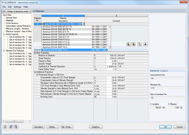
- Integration of parameters from National Annexes (NA) of the following countries:
-
DIN EN 1999-1-1/NA:2010-12 (Germany)
-
NBN EN 1999-1-1/ANB:2011-03 (Belgium)
-
DK EN 1999-1-1/NA:2013-05 (Denmark)
-
SFS EN 1999-1-1/NA:2016-12 (Finland)
-
ELOT EN 1999-1-1/NA:2010-11 (Greece)
-
IS EN 1999-1-1/NA:2010-03 (Ireland)
-
UNI EN 1999-1-1/NA:2011-02 (Italy)
-
LST EN 1999-1-1/NA:2011-09 (Lithuania)
-
UNI EN 1999-1-1/NA:2011-02 (Italy)
-
NEN EN 1999-1-1/NB:2011-12 (Netherlands)
-
PN EN 1999-1-1/NA:2011-01 (Poland)
-
SS EN 1999-1-1/NA:2011-04 (Sweden)
-
STN EN 1999-1-1/NA:2010-01 (Slovakia)
-
BS EN 1999-1-1/NA:2009 (the United Kingdom)
-
STN EN 1999-1-1/NA:2009-02 (Slovakia)
-
CYS EN 1999-1-1/NA:2009-07 (Cyprus)
-
- Serviceability limit state design for characteristic, frequent, or quasi-permanent design situation
- Consideration of transverse welds
- Variety of cross-sections provided; for example, I‑sections, C‑sections, rectangular hollow sections, square sections, angles with equal and unequal legs, flat steel, round bars
- Clearly arranged result tables
- Automatic cross-section optimization
- Detailed result documentation with references to the design equations used and described in the standard
- Filter and sorting options for results, including result lists by member, cross‑section, and x‑location, or by load cases, load combinations, and result combinations
- Result window of member slenderness and governing internal forces
- Parts list with weight and solid specifications
- Seamless integration in RFEM/RSTAB
- Metric and imperial units
Geometry, material, cross-section, action, and imperfection data are entered in clearly arranged input windows:
Geometry
- Quick and convenient data input
- Definition of support conditions based on various support types (hinged, hinged movable, rigid, and user-defined, as well as lateral on upper or bottom flange)
- Optional specification of warping restraint
- Variable arrangement of rigid and deformable support stiffeners
- Possibility to insert hinges
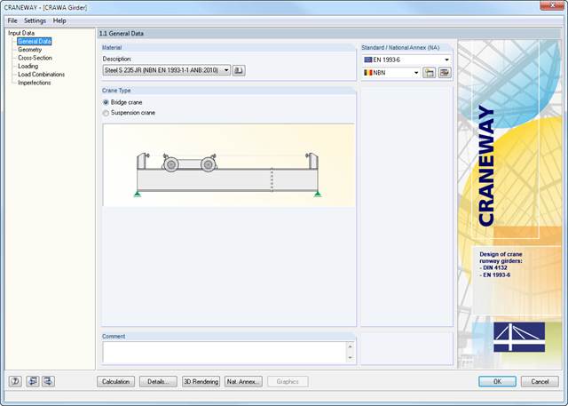
CRANEWAY Cross-Sections
- I-shaped rolled cross-sections (I, IPE, IPEa, IPEo, IPEv, HE-B, HE-A, HE-AA, HL, HE-M, HE, HD, HP, IPB-S, IPB-SB, W, UB, UC, and other cross-sections according to AISC, ARBED, British Steel, Gost, TU, JIS, YB, GB, and others) combinable with section stiffener on the upper flange (angles or channels) as well as rail (SA, SF) or splice with user-defined dimensions
- Unsymmetrical I-sections (type IU) also combinable with stiffeners on the upper flange as well as with rail or splice
Actions
It is possible to consider the actions of up to three simultaneously operated cranes. You can simply select a standard crane from the library. You can also enter data manually:
- Number of cranes and crane axles (maximum of 20 axles per crane), center distances, position of crane buffers
- Classification in damage classes with editable dynamic factors according to EN 1993-6, and in lifting classes and exposure categories according to DIN 4132
- Vertical and horizontal wheel loads from self-weight, hoist load, mass forces from drive, as well as loads from skewing
- Axial loading in driving direction as well as buffer forces with user-defined eccentricities
- Permanent and variable secondary loads with user-defined eccentricities
Imperfections
- The imperfection load applies in compliance with the first natural vibration mode - either identically for all load combinations to be designed, or individually for each load combination, as mode shapes may vary depending on the load.
- Convenient tools available for scaling the mode shapes (rise determination of inclination and precamber).

- Design of knee joints, T-joints, cross joints, and continuous column connections with I-shaped sections
- Import of geometry and load data from RFEM/RSTAB or manual specification of the connection (for example, for recalculation without an existing RFEM/RSTAB model)
- Flush top connections or connections with bolt row in extension
- Design of positive and negative frame joint moments
- Various inclinations of right and left horizontal beams as well as application to frames of duopitch and monopitch roofs
- Consideration of additional flanges in a horizontal beam, for example for tapered sections
- Symmetrical and asymmetrical T-joints or cross joints
- Two-sided connection with different cross-section depth on the right and left
- Automatic preliminary design of bolt layout and required stiffening
- Optional design mode with possibility to specify all bolt spacing, welds, and sheet thicknesses
- Screwability check with adjustable dimensions of used wrenches
- Connection classification by stiffness and calculation of the spring stiffness of connections considered in the internal forces determination
- Check up to 45 individual designs (components) of the connection
- Automatic determination of governing internal forces for each individual design
- Controllable connection graphics in rendering mode with specifications of material, sheet thickness, welds, bolt spacing, and all dimensions for construction
- Integrated and flexibly extensible settings of National Annexes according to EN 1993-1-8 standard
- Automatic conversion of internal forces from structural analysis into respective sections, also for eccentric member connections
- Automatic determination of initial stiffness Sj,ini of the connection
- Detailed plausibility check of all dimensions, including specifications of input limits (for example, for edge distances and hole spacing)
- Optional application of compression forces to a column through contact
- Possibility to update the cross-section depth of horizontal beams in case of tapered connections after connection geometry optimization in RF-/FRAME-JOINT Pro
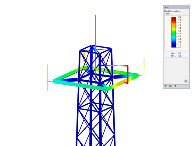
- Consideration of the data from the other RF-/TOWER modules (Structure, Equipment, Loading, Effective Lengths)
- Automatic cross-section classification
- Design of triangular and quadrilateral lattice towers according to EN 1993-1-1, EN 1993-3-1, and EN 50341, including National Annexes
- Flexural buckling analysis of truss members based on the effective slenderness considering bracing and support conditions
- Design of equipment such as platforms according to EN 1993-1-1
- Clearly arranged display of results including relevant parameters in result tables
- Parts list result window
- Creation of a verifiable printout report
- Design of members and sets of members for tension, compression, bending, shear, torsion, and combined internal forces
- Stability analysis of buckling, torsional, and flexural-torsional buckling
- Automatic determination of critical buckling loads and critical buckling moments for general load applications and support conditions by means of a special FEA program (eigenvalue analysis) integrated in the module
- Alternative analytical calculation of the critical buckling moment for standard situations
- Optional application of discrete lateral supports to beams and continuous members
- Automatic cross-section classification
- Serviceability limit state design (deflection)
- Cross-section optimization
- A wide range of available cross-sections, such as rolled I-sections; channel sections; T-sections; angles; rectangular and circular hollow sections; round bars; symmetrical and asymmetrical, parametric I-, T-, and angle sections; double angles
- Clearly arranged input and result windows
- Detailed result documentation including references to design equations of the used standard
- Various filter and sorting options of results, including result lists by member, cross-sections, x-location, or by load case, load and result combination
- Result tables of member slenderness and governing internal forces
- Parts list with weight and solid specifications
- Seamless integration in RFEM/RSTAB
- Cross-section designs of members and sets of members for tension, compression, bending, shear, torsion, and combined internal forces
- Stability analysis of buckling, torsional, and flexural-torsional buckling
- Automatic determination of critical buckling loads and critical buckling moments for general load applications and support conditions by means of a special FEA program (eigenvalue analysis) integrated in the module
- Alternative analytical calculation of the critical buckling moment for standard situations
- Optional application of discrete lateral supports to continuous members
- Automatic cross-section classification
- Serviceability limit state design (deflection)
- Cross-section optimization
- A wide range of available cross-sections, such as rolled I-sections, channel sections, T-sections, angles, rectangular and circular hollow sections, round bars, symmetrical and asymmetrical, parametric I-, T-, and angle sections, and many others.
- Clearly arranged input and result windows
- Detailed result documentation including references to design equations of the used standard
- Various filter and sorting options of results, including result lists by member, cross-sections, x-location, or by load case, load and result combination
- Result window of member slenderness (optional) and governing internal forces
- Parts list with weight and solid specifications
- Seamless integration in RFEM/RSTAB
- Design of members and sets of members for tension, compression, bending, shear, combined internal forces, and torsion
- Stability analysis of buckling, torsional, and flexural-torsional buckling
- Automatic determination of critical buckling loads and critical buckling moments for general load applications and support conditions by means of a special FEA program (eigenvalue analysis) integrated in the module
- Alternative analytical calculation of the critical buckling moment for standard situations
- Optional application of discrete lateral supports to beams and continuous members
- Automatic cross-section classification
- Serviceability limit state design (deflection)
- Cross-section optimization
- A wide range of available cross-sections, such as rolled I-sections; channel sections; T-sections; angles; rectangular and circular hollow sections; round bars; symmetrical and asymmetrical, parametric I-, T-, and angle sections; double angles
- Clearly arranged input and result windows
- Detailed result documentation including references to design equations of the used standard
- Various filter and sorting options of results, including result lists by member, cross-sections, x-location, or by load case, load and result combination
- Result tables of member slenderness and governing internal forces
- Parts list with weight and solid specifications
- Seamless integration in RFEM/RSTAB
- Units metric and imperial
- Full integration in RFEM/RSTAB including import of all relevant internal forces
- Intelligent presetting of flexural buckling-specific design parameters
- Automatic determination of the distribution of internal forces and classification according to DIN 18800, Part 2
- Optional import of buckling lengths from the RF-STABILITY/RSBUCK add-on module. For this, a comfortable graphical selection of the relevant buckling mode is possible
- Optimizing Cross-Sections
- Optional calculation according to both design methods of DIN 18800, Part 2
- Automatic determination of the most unfavorable design location, also for tapered members
- Check of c/t-limit values according to DIN 18800, Part 1
- Design of any thin-walled RFEM/RSTAB or SHAPE-THIN section for compression and bending without interaction according to the elastic-plastic method
- Design of I-shaped rolled and welded sections, I-like sections, box sections, and pipes subjected to bending and compression with iteration according to the elastic-plastic method
- Clearly arranged, comprehensible design checks with all intermediate values in the short and long forms
- Parts list of members and sets of members
- Direct export of all results to MS Excel
- A manual with manually calculated examples