To generate a finite volume mesh for CFD, the model must be topologically correct. In RWIND 2, model boundaries are defined by triangles. The term "topologically correct" means, that these triangles must form a closed triangular mesh – each mesh edge has exactly two adjacent triangles and the triangles must not intersect or touch each other except the common edges and vortices. In fact, the exact definition of a "topologically correct" model is more complicated, but we do not want to go into all the details here.
Typical CAD models are often not topologically correct. Triangles of a 3D object intersect with triangles of other objects, the model boundary is not closed, and so on. The pre-processing of such models for a CFD analysis can be very extensive and requires 60-80% of engineer’s time. Facilitating this work is therefore one of the strongest features of RWIND 2. It has been achieved by implementation of so called simplified model. The simplified model is represented by a special mesh "shrink-wrapping" the original model. This mesh is topologically correct and can therefore be used as a model boundary for the generation of a 3D finite volume mesh for CFD calculation.
Model Mesh Types
In RWIND 2 there are 5 types of meshes, each with its own role in the calculation process. Here is an overview of them, sorted from the RFEM 6 original model mesh to the RWIND 2 computational mesh:
Original Model Mesh
Meshes created based on the original FEM mesh in RFEM 6. There are two types:
- M1: Mesh based on the FEM mesh of RFEM 6 model or the imported stl model.
- M2: Refined mesh for better graphical display of results on the original model. RWIND 2 refines the original model mesh for better transition of the results from the surface computational mesh to the original model.
Simplified Model Mesh
The mesh generated by RWIND 2:
- M3: The mesh created by shrink-wrapping topologically improves the M1 mesh. The shrink-wrapping process creates a simplified model of the complex structure, reducing the level of detail of the original model. The shrink-wrapping mesh is then used as the input boundary mesh for the CFD calculation in OpenFOAM.
Computational Model Mesh
Meshes generated by OpenFOAM. There are two types:
- M4: Surface computational mesh created by OpenFOAM based on the M3 mesh, the basis (boundary mesh) for generating the M5 volume 3D mesh. After the calculation the surface results are displayed on this surface mesh (computational mesh).
- M5: Volume 3D mesh generated by snappyHexMesh based on the boundary surface mesh (M4). To learn more about the mesh generation process follow the link here. The M5 mesh fills the 3D flow domain around the model and after the calculation, the flow field results are displayed on it.
Model Simplification
The simplified model automatically corrects most of the problems that would have to be corrected manually otherwise. These problems include:
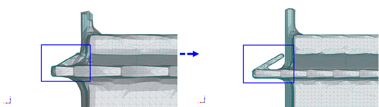
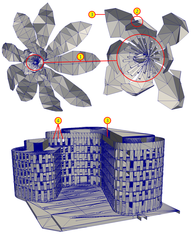
- Unnecessary details (see Point 1 in the image Topological Imperfections): details that are not relevant to the given simulation and could cause calculation instability due to insufficiently fine discretization.
- Intersection of triangles (see Point 2)
- Open edges and surfaces with zero thickness (see Point 3)
- Openings through which the fluid (wind) flows into the interior of the building (see Point 4)
The image of simplified models below shows some examples of automatically corrected models.
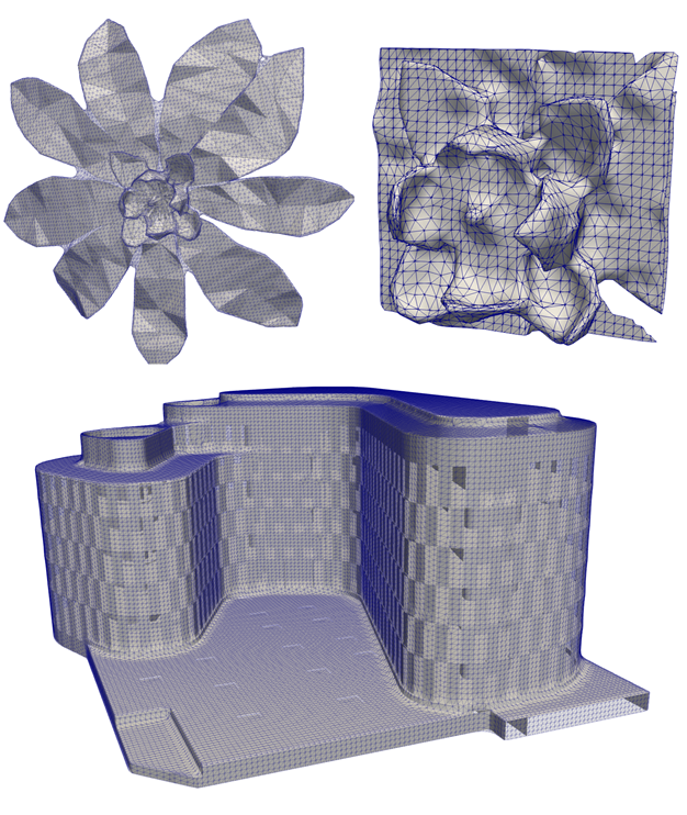
When simplifying the model, it is possible to specify the level of detail as well as the maximum size of the openings to be closed. Using a simplified model to determine the wind load on a building is based on the following assumption: if the simplified model approximates the shape of the original model well, the load calculated for the simplified model will also approximate the correct values.
Although the use of the simplified model is suggested in most cases, the user can disable this option and use the imported model boundaries for calculation. However, this option is recommended only for advanced users experienced in CFD analyses.
Result Extrapolation
After the calculation, we have the results on the computational mesh and need to transfer them to the surface of the original model (i.e., the "Original Mesh"). For that, RWIND uses an extrapolation process described below.
The extrapolation process can be devided into two main sections:
1. Locating the Boundary Triangles
The extrapolation process starts by locating the boundary triangles of the mesh on the model surface. We look for triangles whose centeroid is close enough to the original mesh. During this process certain criteria are taken into account, e.g. the triangles must not overlap each other, etc.
2. Extrapolation of Pressure on the Original Model Mesh
Then, for each boundary triangle of the original mesh, we find a suitable point on the computational mesh and find the pressure value there.
To find a point on the computational mesh, we first construct the normal n at the center of the triangle S, then find a resulting point at the intersection of the normal n with the triangle of the computational mesh, see image below. If the resulting point cannot be found in this way, then the nearest possible point in the surrounding area is taken.
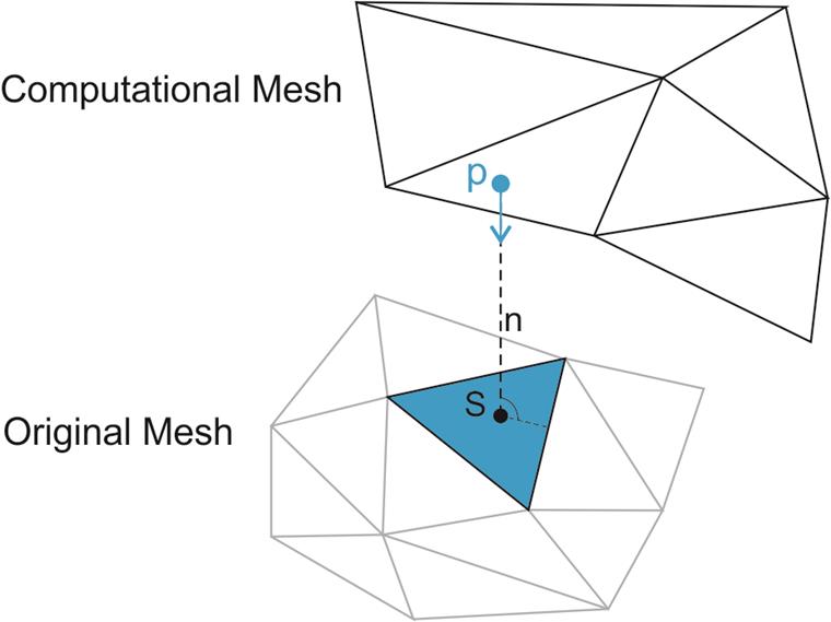
If we manage to find a suitable point on the computational mesh, we use the pressure value at that point and transfer it to the whole triangle of the original mesh, see image. The result of this process is the pressure values in each triangle of the original model mesh. On the surface of the model these values are non-zero (positive values = pressure, negative values = suction) and on the rest of the model the pressure is zero. It is then possible to calculate the forces acting at the centres of the triangles due to the pressure induced by the surface of the triangles. The direction of the force is in the direction normal to the triangle.
Checking the Computational Mesh before Calculation
RWIND has the computational mesh parameters set very well by default for many models (level of detail, etc.), but the range of RWIND applications is very wide and not all models may find the default settings ideal.
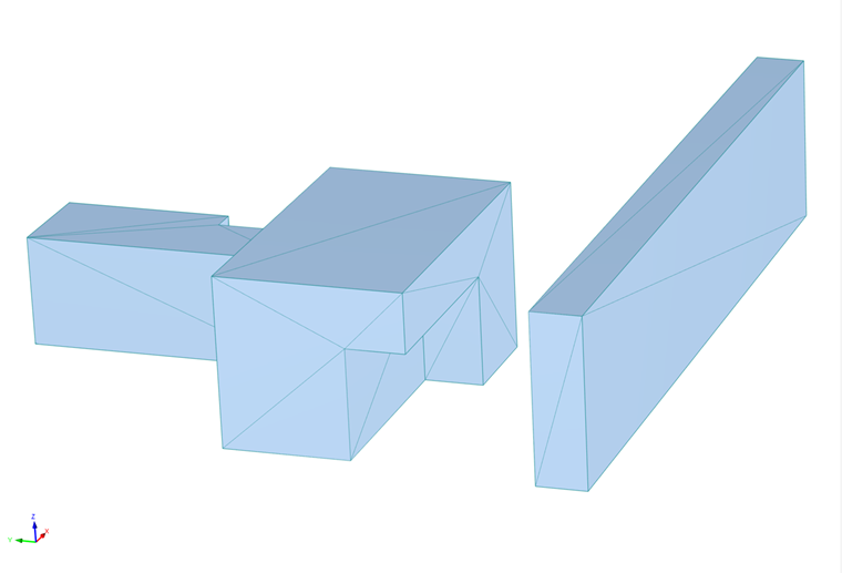
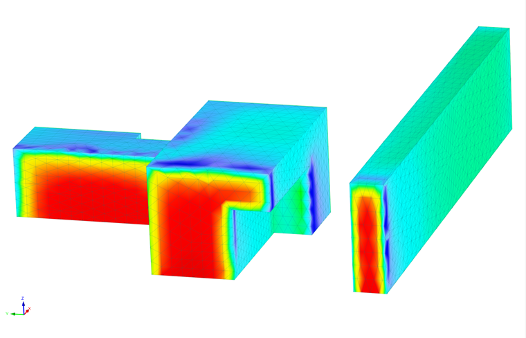
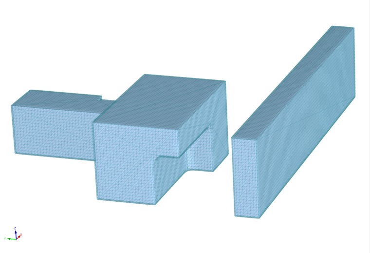
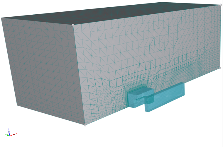
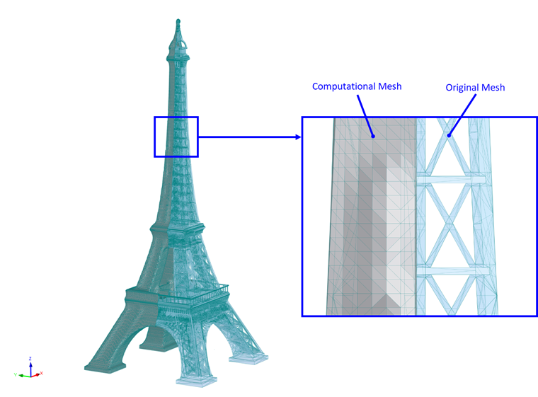
If we suspect that our model requires more specific settings (e.g. building details play a significant role in the wind flow simulation), it is a good idea to check the computational mesh before calculating. The following image shows how to display both meshes.
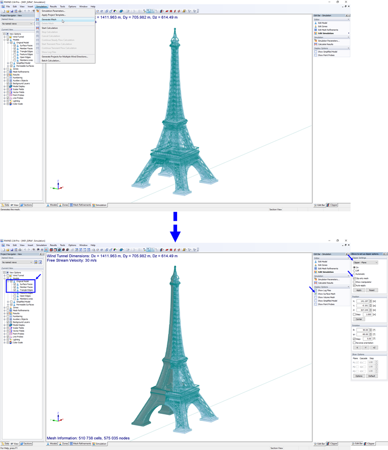
Some tips on what to look out for:
- Whether the generated computational mesh sufficiently captures the geometry of the model, whether the simplification is too high, see image below.