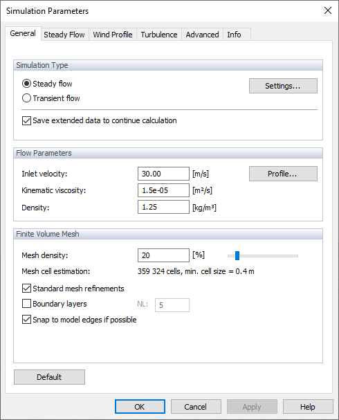
Simulation Type
In this section we can choose between two types of simulation, steady flow simulation and transient flow simulation, the theoretical background can be found in chapter Steady Flow and Transient Flow. The parameters of both simulations are described in detail in the following chapters Steady Flow and Transient Flow.
RWIND 2 provides a new option to continue the calculation of a given project even after the calculation is interrupted and the project is closed. To be able to continue the calculation even after the project is closed and to open it again, you need to select "Save extended data to continue calculation" option. This has to be done before saving the project data while the data still exist in the working directory, that is, when the calculation has just been finished.
Flow Parameters
The "Inlet velocity" represents the wind speed entering the wind tunnel. The
![]() button enables you to define the wind speed as a function of the height. You can enter the chart values as described in Chapter Wind Profile below. The value of the "Kinematic viscosity" describes the resistance of the air against deformation. It is defined as the ratio of the viscosity to the "Density" of the air.
button enables you to define the wind speed as a function of the height. You can enter the chart values as described in Chapter Wind Profile below. The value of the "Kinematic viscosity" describes the resistance of the air against deformation. It is defined as the ratio of the viscosity to the "Density" of the air.
Finite Volume Mesh
The "Mesh density" to be applied around the model is controlled by percentage reference. This specific refinement is utilized for the model simplification and the flow calculation. The default density (20%) normally results in a relatively low number of finite volume mesh cells and a relatively fast calculation. The minimum percentage is 10%. It entails a rather coarse mesh with the smallest number of volumes. The higher the density of the mesh, the smaller the size of the finite volume cells will be. The results are accordingly more precise, but the calculation will need more time due to the greater number of volumes. Setting the maximum mesh density (100%) leads to very fine meshes with millions of volumes. The calculation of 3D flow on such meshes is on the edge of the capabilities of current PCs, with a calculation time of several hours to several days.
You can enter the mesh density or modify it with the slider. The "Mesh cell estimation" below gives the corresponding number of finite volume cells and the minimum cell size.
The "Mesh refinement" type can be defined for curvatures of the surfaces (fine mesh only close to sharp edges of the model) or globally for a distance from the surfaces (fine mesh on entire boundary surfaces). The first option is set as default, because it produces meshes with a lower number of finite elements.
Consider the "Standard Mesh Refinements" option, which allows you to disable the generation of standard mesh refinements and enable user-defined refinements of sites and their placement, see Chapter Mesh Refinements.
The "Boundary layers" option controls whether the finite volume mesh next to the surfaces of the model is refined in a special way. This refinement gives better results near the boundaries of the model. As the number of finite volumes is increased considerably by the layers of small volumes, however, the option is disabled by default. We highly recommend activating the boundary layers and defining the number of layers NL, however, when the surface roughness is to be taken into account.
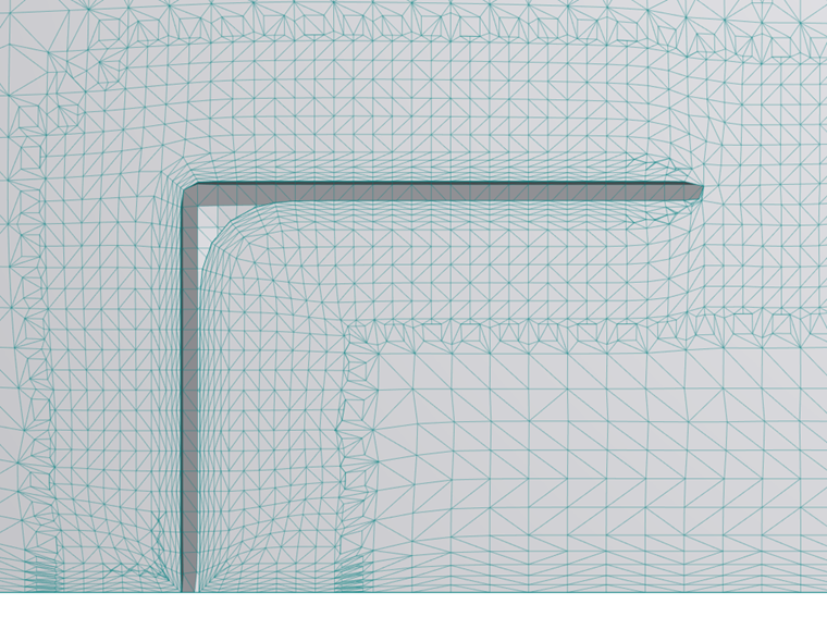
The "Snap to model edges" option enables you to align the mesh with the borders of the model.