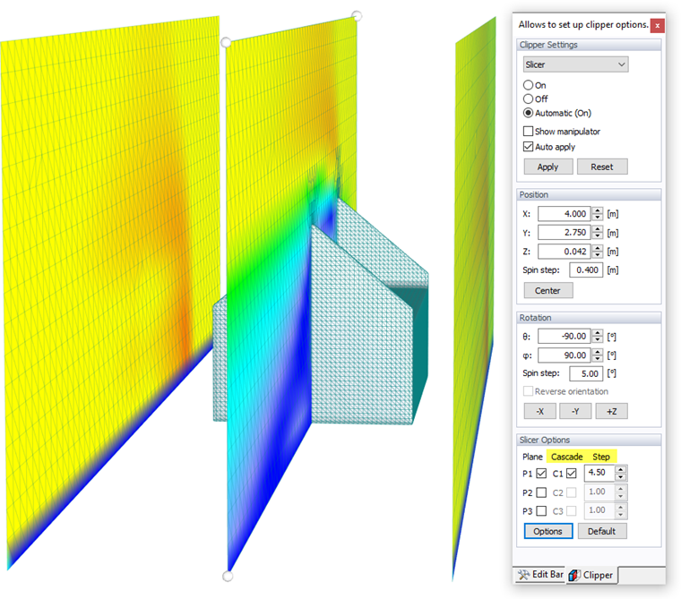
All scalar field results, such as Pressure Field and Velocity Field , as well as the Velocity Vectors are displayed in a "Slicer" plane. It represents a planar section through the air flow within the wind tunnel.
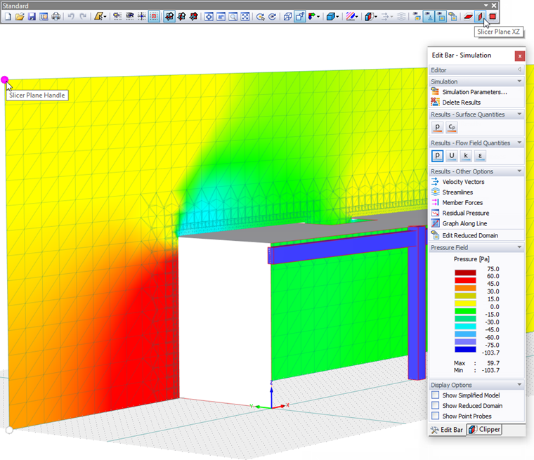
By default, the slicer plane is located in the center of the wind tunnel and aligned parallel to one of the global planes (XY, XZ, YZ). You can change the plane by clicking the corresponding button
![]() in the toolbar.
in the toolbar.
To move the slicer to a different position, use one of the four bullets shown in the corners of the slicer plane (Slicer Plane Handle, see the image above). When you pull the plane along a wind tunnel line, the results are dynamically updated for the new slicer plane.
If you need an inclined plane to evaluate the results, select the "Clipper" tab of the panel. Either define the "Rotation" about the relevant axis manually in the corresponding panel section or select the "Show Manipulator" option in the "Clipper Settings" section to adjust the plane graphically.
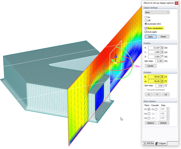
Use the arcs shown in the slicer center to rotate the plane about its longitudinal or transversal axis. The corresponding angle is updated in the panel.
Activate the "Cascade" option in the "Slicer Options" section of the panel to create a group of parallel planes ("slices") within the wind tunnel. You can define the distance between each by clicking the
![]() button. Alternatively, use the "Slicer Options" in the "Options" menu to open the corresponding dialog box.
button. Alternatively, use the "Slicer Options" in the "Options" menu to open the corresponding dialog box.
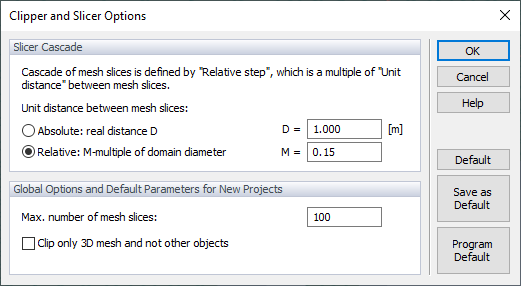
In the "Slicer Cascade" section, you can define the unit distance between each parallel plane by an "Absolute" value or a "Relative" parameter (the effective distances are controlled in the "Clipper" tab using the "Step" factors).
The "Options" section controls the maximum number of parallel planes. It is a global setting that applies to all projects.