Sections can be applied to the surfaces of the model. They enable you to display parts of the result meshes and obtain local results, for example, a drag force acting on the section. These results can be examined for any part of a model, that is, for any subset of model triangles.
By means of sections, you can also control which parts of the topology are displayed. The parts can be shown exclusively or hidden, similarly to the "Visibility" options available in RFEM 6 / RSTAB 9.
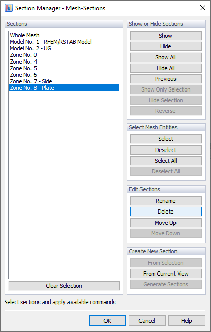
The sections are managed in a separate tab of the navigator. By default, sections are created automatically for the zones, each representing a material or a part (see Chapter Zones).
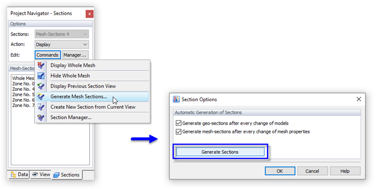
To also use the zones for the results, it is necessary to create mesh sections. Click the
![]() button. In the menu, select the "Generate Mesh Sections" option. The "Section Options" dialog box appears. Click the
button. In the menu, select the "Generate Mesh Sections" option. The "Section Options" dialog box appears. Click the
![]() button and then close the dialog box.
button and then close the dialog box.
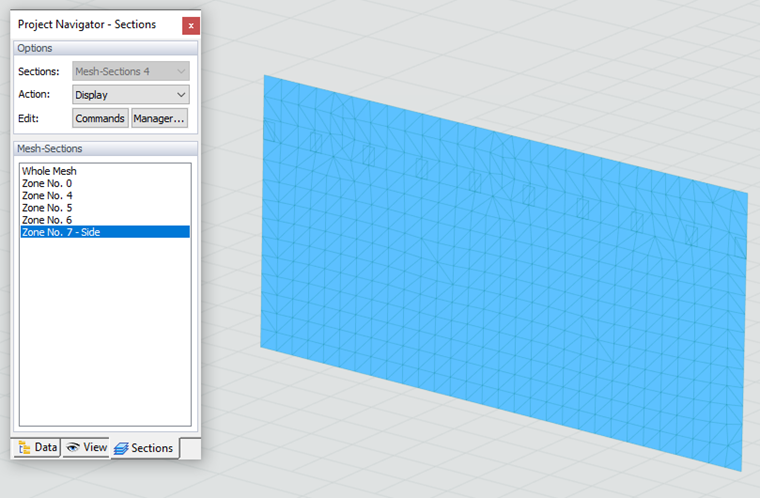
Now, you can select a zone in the "Mesh Sections" list and examine its surface quantity results.
For each zone in the "Mesh Section," there are "Display Options" in the "Edit Bar" menu.
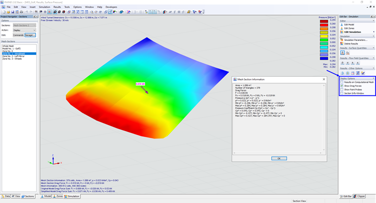
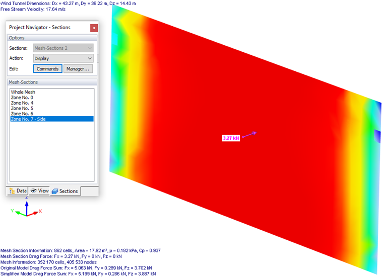
Here you can easily display the "Drag Force" or the "Mesh Section Information" for the zone, see the image Display Options.
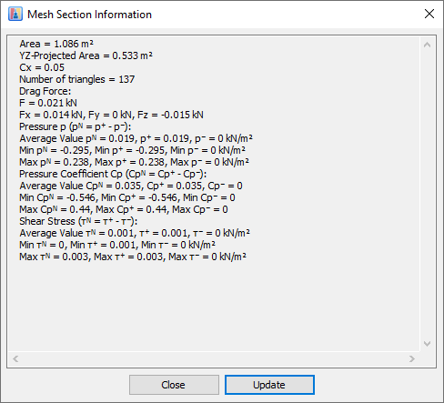
The Mesh Section Information window contains basic information about the zone, the size of the area, and the number of triangles in the area. Then, there are the results of the "Drag Force" quantities, the resultant force (F), and its components (Fx, Fy, Fz).
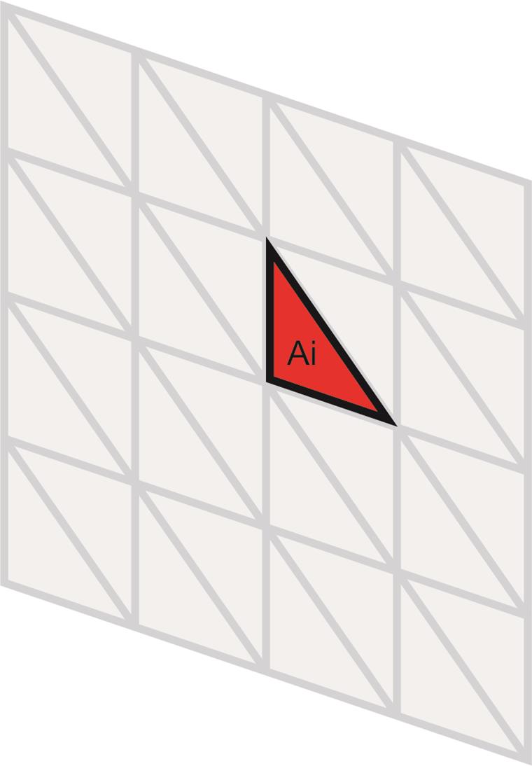
Next, There are values on the triangles of the surface mesh. The mesh section is divided into triangles, each triangle has "front" and "back" values that may be different.
The "netto" value of the quantity (pN) is calculated as the weighted average of the (pN) values calculated for each triangle belonging to the zone, calculated from the (p+) value on the front side and the (p-) value on the back side of the triangles. The average value calculated over all triangles of the mesh section is given by the formula:
Furthermore, the CpN coefficients, shear stress TN, and the maximum and minimum values of those quantities (such as Max pN, Min pN, Max TN, Min TN, and so on) are shown. The maximum/minimum values are the maxima/minima of the variables on the front/back of each triangle belonging to the zone, e.g. Max Cp+ is the max value of Cp in front side of each triangle belonging to the zone.
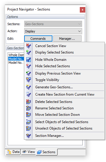
Geo Sections
Each model – primary or secondary – represents a Geo section. They are available when selecting the "Model" tab of the work window. Use the
![]() button to create sections and work with them.
button to create sections and work with them.
Mesh Sections
The mesh sections represent all zones that were created automatically or defined manually (see Chapter Zones). They are available when selecting the "Zones" tab of the work window. To modify or delete sections, use the
![]() button.
button.