List
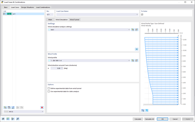
All load cases (LC) of the model are listed on the left of the "Load Cases" tab. There, you can create a new LC, copy or delete it. The other functions available from the buttons at the end of the list are described in the table below.
|
|
Creates a new load case |
|
|
Copies the selected load case(s) |
|
|
Adds loads to a new or existing load case |
|
|
Selects all load cases |
|
|
Inverts the selection of load cases in the list |
Settings
In this area, assign the "Wind Simulation Analysis Settings" (WA) to the selected load case.
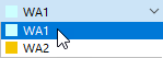
You can select the "WA" from the list or create a new wind simulation analysis settings type using the
![]() button. To edit the selected wind simulation analysis settings, click the
button. To edit the selected wind simulation analysis settings, click the
![]() button. The "Wind Simulation Analysis Settings" dialog box is described in Chapter Wind Simulation Analysis Settings.
button. The "Wind Simulation Analysis Settings" dialog box is described in Chapter Wind Simulation Analysis Settings.
Calculation in RWIND 2
You can also start RWIND 2 by clicking the
![]() button in the right corner of the "Settings" area. This function exports the model data relating to one of the load cases to the RWIND 2 program.
button in the right corner of the "Settings" area. This function exports the model data relating to one of the load cases to the RWIND 2 program.
There, you can review the settings of the wind tunnel, mesh, simplification of the model, and so on. If necessary, you can adjust the parameters. Here is an example of a common procedure:
- Start RWIND 2 calculation.
- Check the results.
- Quit RWIND 2 and return to RFEM 6 / RSTAB 9.
- Calculate the remaining load cases, if applicable.
- Inspect the imported loads in the work window and tables.
- Combine the wind load case(s) with other load cases in load and result combinations, if applicable.
- Finally, start the calculation of the deformations and internal forces.
Find more information in a Knowledge Base article.
The
![]() button is used for a new calculation, but also for back-checking the simulation results after having calculated one LC
button is used for a new calculation, but also for back-checking the simulation results after having calculated one LC
![]() or all LCs
or all LCs
![]() .
.
Wind Profile
In this area, assign the "Wind Profile" to the selected load case. You can create a new wind profile by clicking the
![]() button. To edit the selected wind profile, use the
button. To edit the selected wind profile, use the
![]() button. The "Wind Profile" dialog box is described in Chapter Wind Profile.
button. The "Wind Profile" dialog box is described in Chapter Wind Profile.
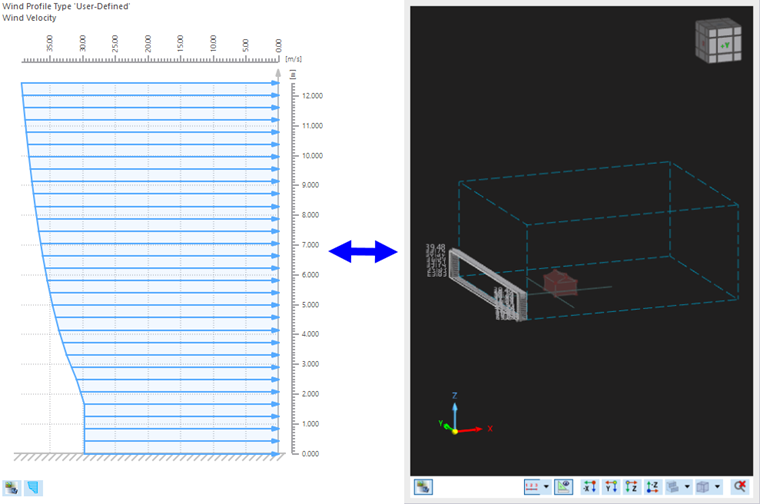
The wind profile is displayed in the right part of the window. You can switch between the velocity profile and the turbulence intensity profile using the
![]() button. The
button. The
![]() button enables you to switch between the Wind Profile and the Wind Tunnel display.
button enables you to switch between the Wind Profile and the Wind Tunnel display.
The "Wind Direction" affects the wind exposure of the model. The angle α to set the wind direction refers to the positive global X-axis of the model. The rotation is defined clockwise about the positive Z-axis.
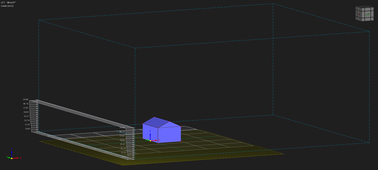
The "Terrain offset" option controls which part of the building is exposed to the wind. The default value is zero, which means that the wind flows around the lowest point of the model. If the model contains a basement storey or foundations, for example, the terrain level should be adapted accordingly. The value refers to the orientation of the global Z-axis: If it points upwards, a positive value moves the model downwards. This means that it is impossible to define an inclined terrain.
If you want to move the model upwards, model the flow under the structure (Model in the air), then you need to define the terrain and then move it downwards. More information about terrain definition and creating the offset, see Chapter Mesh Settings .
In the following picture you can see the final offset of the terrain (horizontal plane).
Options
The "Define experimental data from wind tunnel" option allows you to set experimental pressure at defined "Additional surface result points", checking the checkbox opens a new tab "Experimental Data" for entering data and necessary parameters see chapter Experimental Data for more info.
The second option "Use experimental data for static analysis" allows postprocessing of the specified experimental data using static analysis in RFEM.