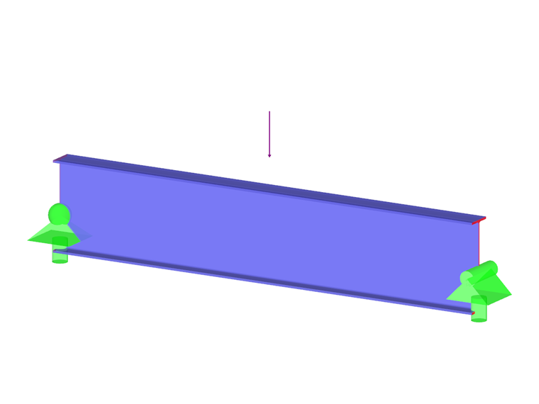
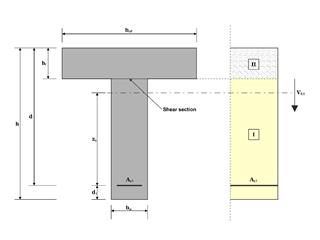
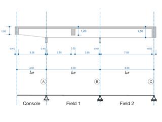
An ASTM A992 W 24×62 beam with end shears of 48.000 and 145.000 kips from the dead and live loads, respectively, is shown in Figure 1. Verify the available shear strength of the selected beam, based on LRFD and ASD.
W-Shape in Strong Axis Shear According to AISC G.1A
Downloads
Do you have any questions?


Length: 00:00:55 min
Length: 00:00:40 min
Length: 00:00:49 min
Length: 00:01:25 min
Length: 00:01:35 min
Length: 00:01:27 min
Length: 00:00:13 min
Length: 00:00:45 min
Length: 00:01:10 min


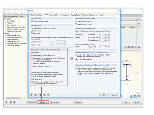
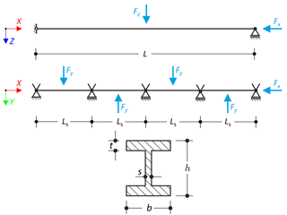
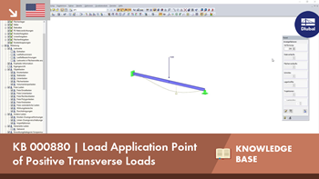
Occasionally, the question arises how to determine the correct load application point of the positive transverse loads in RF-/STEEL EC3 and RF-/STEEL AISC.
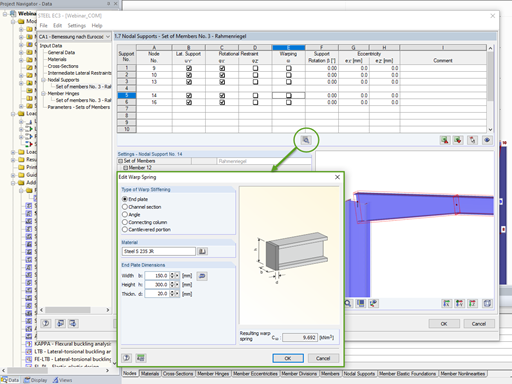
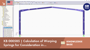
In the case of open cross-sections, the torsional load is removed mainly via secondary torsion, since the St. Venant torsional stiffness is low compared to the warping stiffness. Therefore, warping stiffeners in the cross-section are particularly interesting for the lateral-torsional buckling analysis, as they can significantly reduce the rotation. For this, end plates or welded stiffeners and sections are suitable.
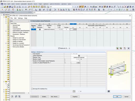
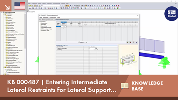
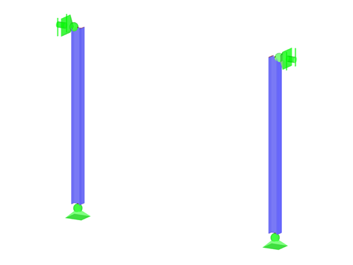
The support conditions of a beam subjected to bending are essential for its resistance to lateral-torsional buckling. If, for example, a single-span beam is held laterally in the middle of the span, the deflection of the compressed flange can be prevented, and a two-wave eigenmode can be enforced. The critical lateral-torsional buckling moment is increased significantly by this additional measure. In the add-on modules for member design, different types of lateral supports on a member can be defined using the "Intermediate supports" input window.
Sometimes a structure needs reinforcement in cases where a new floor is being added, or when an existing member is found to be under design due to a hard-to-predict loading assumption. In many cases, the structural member may not be easily replaced, and reinforcement is implemented to meet the new loading requirement.


Use the "Independent mesh preferred" option in the FE mesh settings to create an independent FE mesh for the integrated objects. This allows you to generate a significantly more detailed and precise FE mesh for individual objects that are integrated into one another.

In the "Edit Section" dialog box, you can display the buckling shapes of the Finite Strip Method (FSM) as a 3D graphic.

In RFEM 6 and RSTAB 9, you have the option to enter "Visual Objects" as guide objects. You can import the file formats 3ds, stl, and obj.
These objects allow you to create a better reference to the dimensions.

Do you have individual column sections and angled wall geometries, and need punching shear design for them?
No problem. In RFEM 6, you can perform punching shear design not only for rectangular and circular sections, but for any cross-section shape.
How do I apply wind load on members of open structures in RFEM 5?
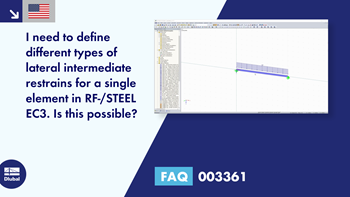
I need to define different types of lateral intermediate restrains for a single element in RF-/STEEL EC3. Is this possible?
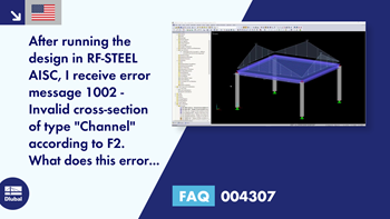
After running the design in RF‑STEEL AISC, I receive error message 1002 - Invalid cross-section of type "Channel" according to F2. What does this error mean?
Is it possible to use the RF‑/STEEL AISC add-on module itself to specify the internal forces, for example, from another calculation or program?
Does RF‑STEEL AISC perform torsion design per Design Guide No. 9?
The performance when starting the programs or working in the program has become noticeably worse. What could be the cause of this?


