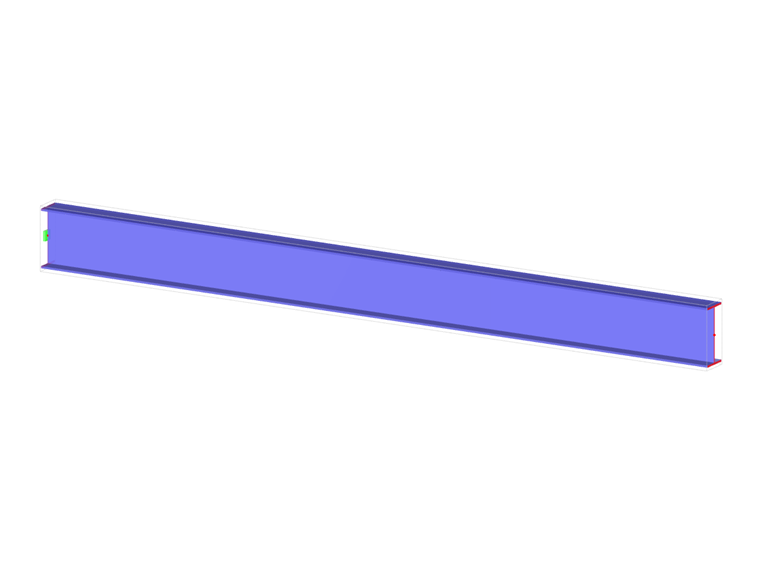
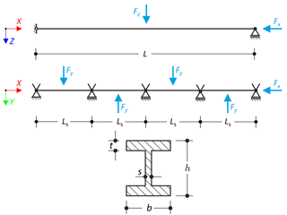
An I-profile cantilever is supported on the left end and loaded by torque. The aim of this example is to compare the fixed support with the fork support and to investigate the behavior of some representative quantities. Comparison is also made to the solution by means of plates. Small deformations are considered, and the self-weight is neglected. Determine the rotation in the midpoint of the cantilever, and in case of the member entity with warping, determine the values of the primary torsional moment, the secondary torsional moment, and the warping moment both on the left end (point A) and the right end (point B).
Cantilever Under Torsion with Warping
Downloads
Do you have any questions?


Length: 00:02:00 min
Length: 00:00:00 min
Length: 00:00:00 min
Length: 00:00:00 min
Length: 00:00:00 min
Length: 00:00:00 min
Length: 00:00:00 min
Length: 00:00:00 min


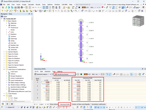
The ASCE 7-22 Standard [1], Sect. 12.9.1.6 specifies when P-delta effects should be considered when running a modal response spectrum analysis for seismic design. In the NBC 2020 [2], Sent. 4.1.8.3.8.c gives only a short requirement that sway effects due to the interaction of gravity loads with the deformed structure should be considered. Therefore, there may be situations where second-order effects, also known as P-delta, must be considered when carrying out a seismic analysis.
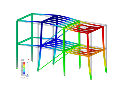
This article presents the basic concepts in structural dynamics and their role in the seismic design of structures. Great emphasis is given to explaining the technical aspects in an understandable way, so that readers without deep technical knowledge can gain an insight into the subject.

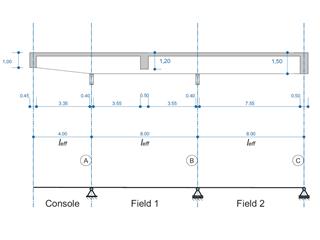
In this article, the calculation of a timber panel wall with the beam panel thickness type is compared with a manual calculation.
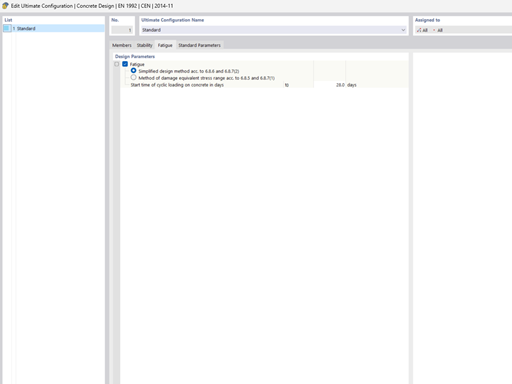
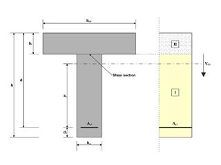
The fatigue design according to EN 1992-1-1 must be performed for the structural components subjected to large stress ranges and/or many load changes. In this case, the design checks for the concrete and the reinforcement are performed separately. There are two alternative design methods available.


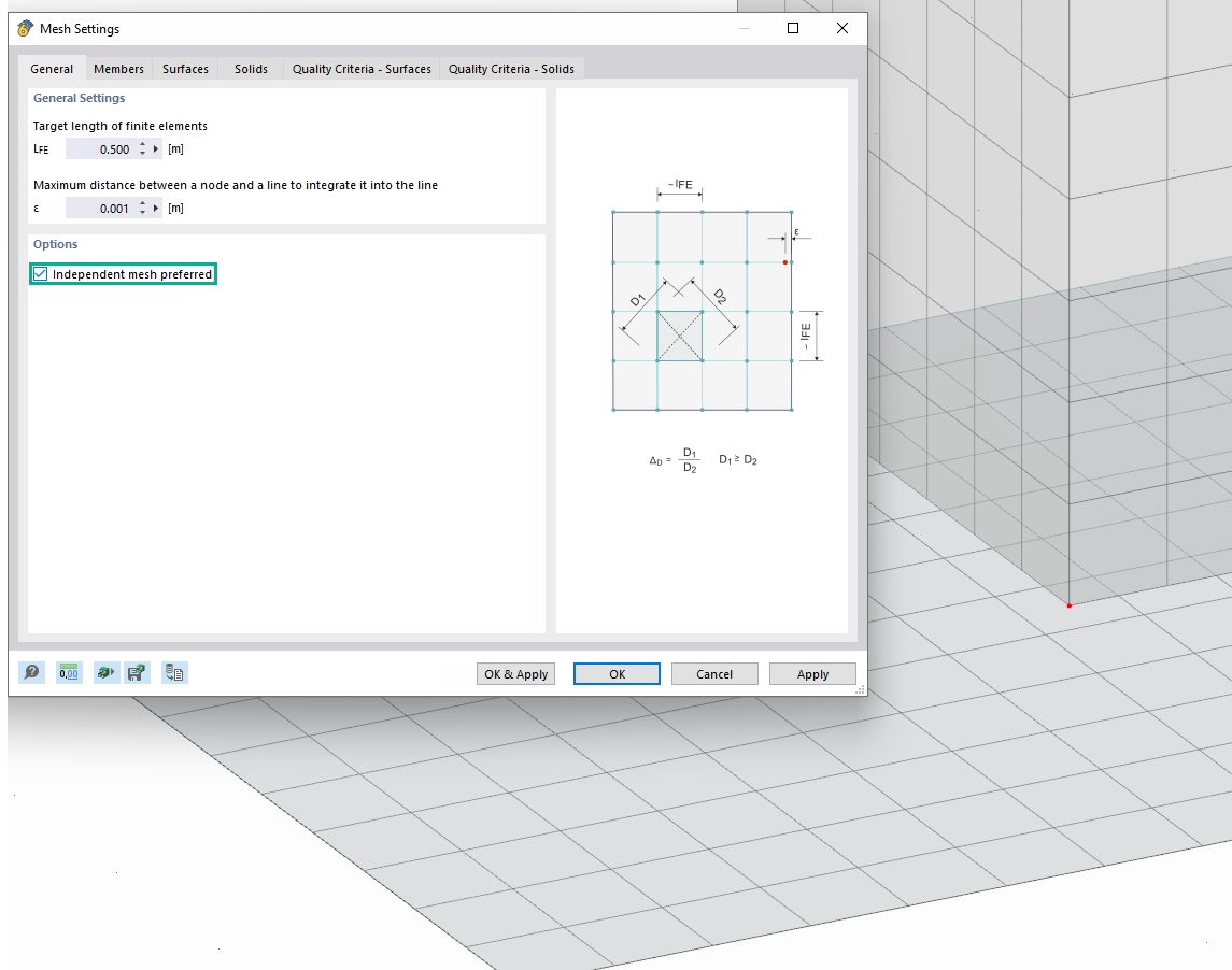
Use the "Independent mesh preferred" option in the FE mesh settings to create an independent FE mesh for the integrated objects. This allows you to generate a significantly more detailed and precise FE mesh for individual objects that are integrated into one another.

In the "Edit Section" dialog box, you can display the buckling shapes of the Finite Strip Method (FSM) as a 3D graphic.

In RFEM 6 and RSTAB 9, you have the option to enter "Visual Objects" as guide objects. You can import the file formats 3ds, stl, and obj.
These objects allow you to create a better reference to the dimensions.

Do you have individual column sections and angled wall geometries, and need punching shear design for them?
No problem. In RFEM 6, you can perform punching shear design not only for rectangular and circular sections, but for any cross-section shape.
Is it possible to refer to the transverse distribution of a load in the case of the isotropic material model? | Masonry | Plastisch Einfluss zu nehmen?
What is the effect of the "Independent FE Mesh Ppreferred" option in the mesh settings?
How do I define a plastic hinge in RFEM 6?
How do I set a uniaxial load transfer on a plate?
Why are not all surfaces transferred when importing surfaces from Rhino into RFEM 6?
How can I exchange data between RFEM 6 / RSTAB 9 and IDEA StatiCa?


