The floor plan forms location calls
of bats. In the course of the construction work for the BUGA, it was necessary to intervene in the habitat of the bats. Careful intervention was the ultimate goal. The Koblenz University of Applied Sciences took up this topic as a design basis and designed the pavilion according to the principles of bionics. The floor plan of the structure shows the sound pressure level depending on the time of the location calls of the noctule bat (native bat species). Since these echolocation calls are not audible to humans, they were displayed in advance as an oscillogram with music editing software.
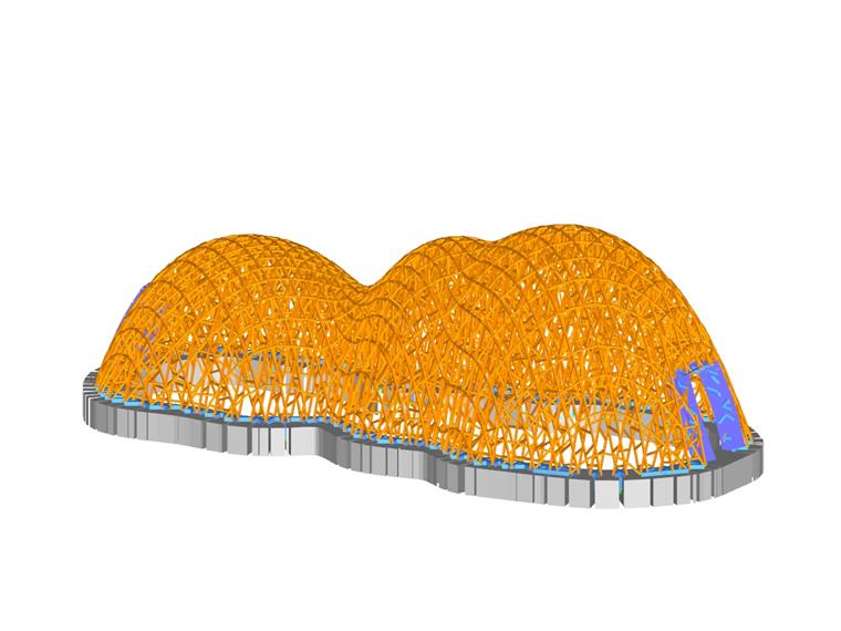
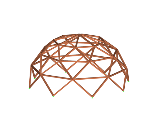
Based on this floor plan, a double-layer hanging support shape was modeled with the "EASY" program system. Such shapes are common in nature because they transfer the loads optimally. The hanging shape was divided into parallel sections in three planes, each at an angle of 60° to the others. Thus, spatially stable triangular and hexagonal grids were created, which are also often found in nature (honeycombs, diatoms, flower shapes, and so on). The refinements of the mesh grid, also following the principles of nature, depend on the magnitude of the static load in the respective area. The choice of the material of the supporting structure was wood, a natural and renewable material. It is recyclable and has a positive ecological balance. In addition, the students should be able to assemble and disassemble the structure by themselves.
Modeling and calculation in RSTAB
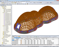
The generated cutting lines were imported into RSTAB via the dxf interface. In each section plane, a member network consisting of a top chord, a bottom chord, and diagonal struts was generated. After applying loads to the structure, the calculation was carried out. After the design, each of the approximately 100 section planes was transferred from RSTAB to Nemetschek Allplan via dxf, where the detailed design was created. The RSTAB model was also exported to the Cinema 4D visualization program, where it was further processed graphically.
| Structural Engineering | University of Applied Sciences, Koblenz Department of Civil Engineering Konrad-Zuse-Straße 1 D-56075 Koblenz, Germany www.hs-koblenz.de |


.png?mw=512&hash=4e74affa9ad0c7b703151c5085ac9b8e59171c23)


.jpg?mw=350&hash=8f312d6c75a747d88bf9d0f5b1038595900b96c1)


