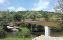
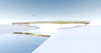
Home Downloads & Info References Customer Projects Pedestrian and Cycling Bridge in Neckartenzlingen, Germany
Pedestrian and Cycling Bridge in Neckartenzlingen, Germany
Customer Project
The S‑shaped pedestrian and cycling bridge across the Neckar river in Germany has a total length of 316 ft and a width of 10 ft with a straight middle part.
Investor |
Town of Neckartenzlingen, Germany www.neckartenzlingen.de |
Building and Structural Planning |
Ingenieurbüro Miebach Lohmar, Germany www.ib-miebach.de |
Traffic Planning |
Ingenieurbüro Blankenhorn Nürtingen, Germany www.ing-blankenhorn.de |
Construction |
Gottlob Brodbeck GmbH & Co. KG Metzingen, Germany www.g-brodbeck.de Schaffitzel Holzindustrie GmbH + Co. KG Schwaebisch Hall, Germany www.schaffitzel.de |
Dimensions
- Length: ~ 316 ft
- Width: ~ 39 ft
- Height: ~ 8 ft
- Number of Nodes: 235
- Members: 152
- Cross-Sections: 14
Model
Both foreland areas are bent in the ground plan and have a radius of approximately 214 ft. In this way, the course of access roads is considered in the ground plan.
Superstructure
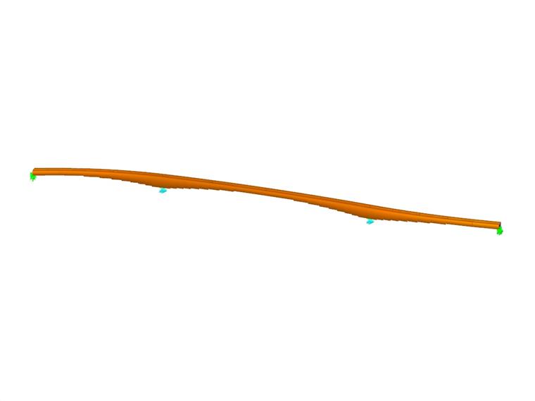
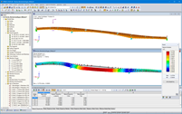
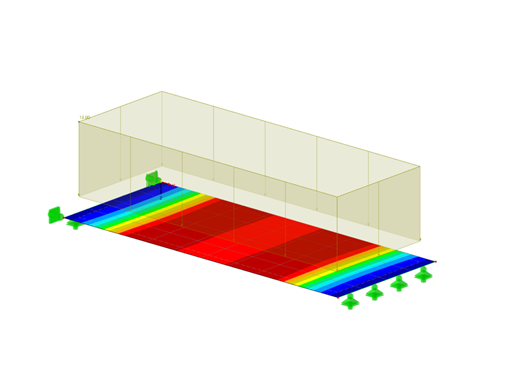
The bridge superstructure consists of two stepped glued‑laminated timber beams coupled to each other and drilled to blocks. It spans three bays with the individual spans of about 85 ft / 146 ft / 85 ft and a total length of 316 ft over the Neckar river.
For efficient material utilization, the cross‑section height is graduated from 31 1/2 in up to 82 in according to the loading. Due to the continuous structure, zero moment distributions result in the main bay. These were modeled as hinge (Gerber) joints. In this way, a reasonable transport size and a simplified assembly of the wooden structural elements were achieved.
Wood Protection
The supporting structure is optimally protected from weather conditions by its geometry (lateral stepping) and the top cover made from precast concrete panels (with lateral overhang, drainage channels below the structural joints and an additional sealing level on the timber beams). In order to verify these wood protection assumptions, a moisture monitoring system was arranged in the area of the highest cross‑section.
Substructure
The substructure consists of reinforced concrete abutments with a bored pile foundation as well as the intermediate supports comprised of reinforced concrete columns built on shallow foundations. In the bridge structure extension, the path continues to a ramp with a throughed supporting structure made of reinforced concrete.
Project Location
Contact us
Do you have questions or need advice?
Contact our free e-mail, chat, or forum support or find various suggested solutions and useful tips on our FAQ page.
Recommended Events
Timber Beam and Surface Structures | Part 1: Modeling, Load Input, Combinatorics
Webinar 05/04/2021 2:00 PM - 3:00 PM CEST
Eurocode 3 | Steel structures according to DIN EN 1993-1-1
Online Training 05/06/2021 8:30 AM - 12:30 PM CEST
Eurocode 2 | Concrete structures according to DIN EN 1992-1-1
Online Training 05/12/2021 8:30 AM - 12:30 PM CEST
Eurocode 5 | Timber structures according to DIN EN 1995-1-1
Online Training 05/20/2021 8:30 AM - 12:30 PM CEST
RFEM | Structural dynamics and earthquake design according to EC 8
Online Training 06/02/2021 8:30 AM - 12:30 PM CEST
Videos
Models to Download
Knowledge Base Articles

New
Once you have determined the final tendon geometry in RF‑TENDON, exporting the model to a CAD program can be useful. For this purpose, the module includes the option to export the file in the .dxf file format.
Screenshots
Product Features Articles

Material Model Orthotropic Masonry 2D
The material model Orthotropic Masonry 2D is an elastoplastic model that additionally allows softening of the material, which can be different in the local x- and y-direction of a surface. The material model is suitable for (unreinforced) masonry walls with in-plane loads.
Frequently Asked Questions (FAQ)
- How to calculate the static depth d when designing the bending of block foundations (calculation as an equivalent beam)?
- I have defined temperature loads, strain loads, or a precamber. As soon as I modify stiffnesses, the deformations are no longer plausible.
- Can the properties, such as B. the cross -section or the surface thickness as well as the material of a surface of an existing element for a new element?
- When should the punching load be determined with the (un)smoothed distribution of the shear forces at the critical perimeter?
- I would like to perform the punching shear design on a column with connected downstand beams as a wall corner or Perform wall end. However, the module applies an internal column. Is it possible to adjust it?
- I am getting the message that my material does not meet the requirements of the current standard. How can I correct this?
- Is it possible to design bidirectional ribbed plates, unidirectional ribbed plates, or hollow core slabs in RFEM?
- In RF-/TIMBER AWC and RF-/TIMBER CSA, I receive the error that says torsion limit exceeded. How do I bypass this error message?
- Why are the values of a column base, head or center on the individual columns only displayed partially for the results from the calculation in RF‑CONCRETE Columns?
- Can I consider a reduction of the stiffness according to the German regulation NCI NA.5.9 in TIMBER Pro?
Customer Projects
Programs Used for Structural Analysis