Do you have any questions about Dlubal products or need assistance in selecting the right one for your project?
I'm here to help. You can easily reach me through the contact options provided below.
Looking forward to hearing from you!


Quick and Easy Automatic Generation of Loads and Combinations
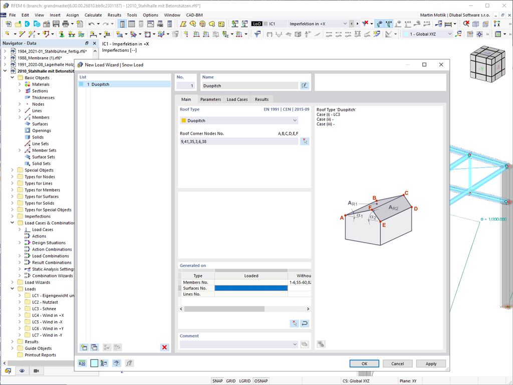
Generation of Snow Loads
Do your structures also have to withstand snowfall? Use the Snow Load Wizard to generate snow loads as member loads or surface loads.
The following standards are available:
-
 EN 1991-1-3 (incl. National Annexes)
 -
 ASCE 7
 -
 NBC
NBC -
 SIA 261
 -
 CTE DB-SE-AE
 -
 GB 50009
 -
 IS 875
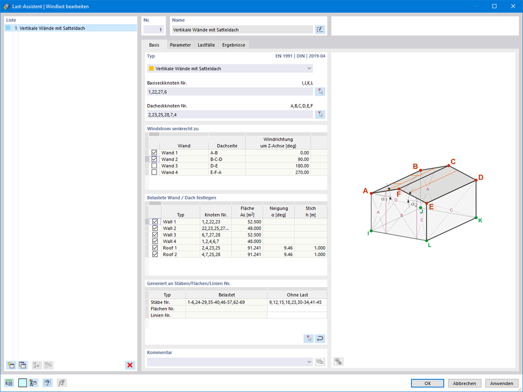
Generation of Wind Loads
Wind loads are also not a problem in your design. You can automatically generate wind loads as member loads or area loads (RFEM) on the following structural components:
- Vertical walls
- Flat roofs
- Monopitch roofs
- Duopitch/troughed roofs
- Vertical walls with duopitch roof
- Vertical walls with flat/monopitch roof
The following standards are available to you:
-
EN 1991-1-4 (including National Annexes)
-
ASCE 7
-
CTE DB-SE-AE
-
GB 50009
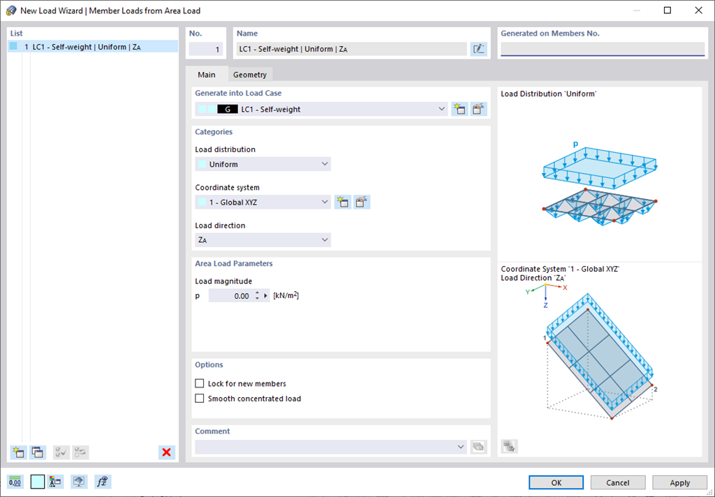
Generating Member/Line Loads from Area Loads
Use all types of loads without any difficulty. You can automatically convert the area loads into member loads or line loads (RFEM).
In the case of member loads from area loads, you have to define a plane via corner nodes or select cells in the graphic. Then the rest works by itself.
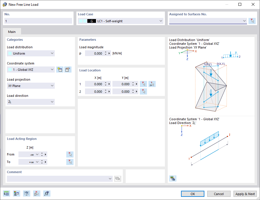
Generating Member Loads from Free Line Loads
Also for pure member models, such as girder grillages, there is a useful feature for you. Here you can define free line loads (for example, from conveyor belts) and transfer them proportionally to members.
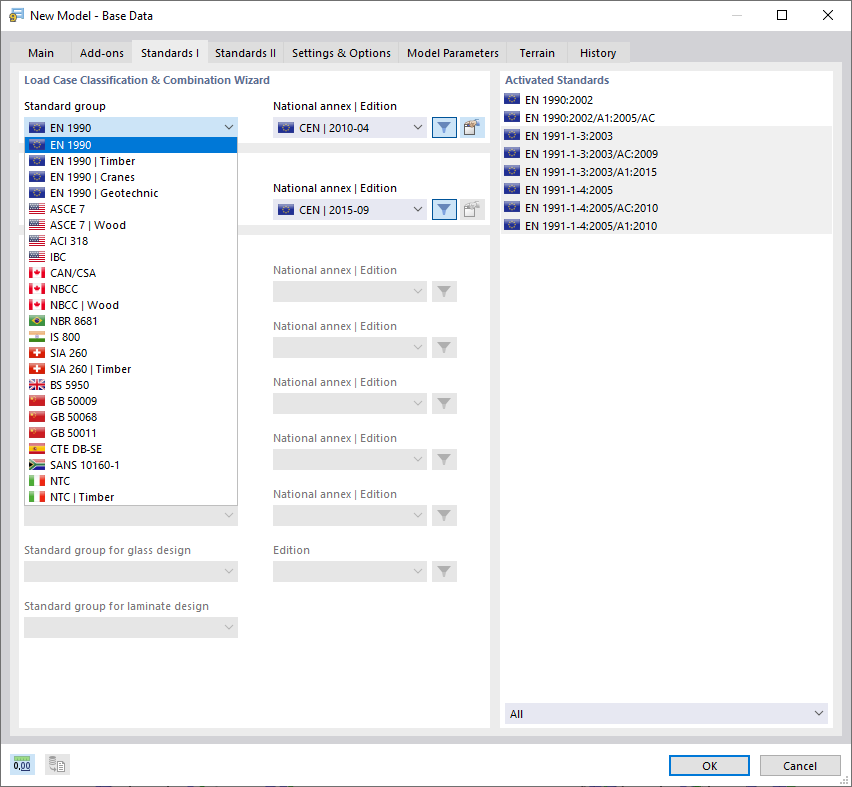
Standards
With Dlubal, you can safely and easily design structures all over the world. Select from a large number of standards in the Base Data. You can also decide whether to create the combinations automatically.
The following standards are available:
-
EN 1990
-
EN 1990 | Timber
-
EN 1990 | Road Bridges
-
EN 1990 | Cranes
-
EN 1990 | Geotechnical Engineering
-
EN 1990 | Base + Timber
-
EN 15512
-
ASCE 7
-
ASCE 7 | Timber
-
ACI 318
-
IBC
-
CAN/CSA
-
NBC
-
NBC | Timber
-
 NBR 8681
 -
IS 800
-
SIA 260
-
SIA 260 | Timber
-
 BS 5950
 -
GB 50009
-
GB 50068
-
GB 50011
-
CTE DB-SE
-
 SANS 10160-1
 -
 NTC
NTC -
NTC | Timber
-
 AS/NZS 1170.0
 -
 SP 20.13330:2016
 -
 TSC | Steel
For the European standards (EC), the following National Annexes are available:
-
 DIN | 2012-08 (Germany)
 -
CEN | 2010-04 (European Union)
-
 BDS | 2013-03 (Bulgaria)
 -
BS | 2009-06 (United Kingdom)
-
 CSN | 2015-05 (Czech Republic)
 -
 CYS | 2010-06 (Cyprus)
 -
 DK | 2013-09 (Denmark)
 -
 ELOT | 2009-01 (Greece)
 -
 EVS-EN 1990:2002+NA:2002 (Estonia)
 -
 IS | 2010-04 (Ireland)
 -
 LST | 2012-01 (Lithuania)
 -
 LU | 2020-03 (Luxembourg)
 -
 LVS | 2015-01 (Latvia)
 -
 MS | 2010-02 (Malaysia)
 -
 NBN | 2015-05 (Belgium)
 -
 NEN | 2011-12 (Netherlands)
 -
 NF | 2011-12 (France)
 -
 NP | 2009-12 (Portugal)
 -
 NS | 2016-05 (Norway)
 -
 ÖNORM | 2013-03 (Austria)
 -
 PN | 2010-09 (Poland)
 -
 SFS | 2010-09 (Finland)
 -
 SIST | 2010-08 (Slovenia)
 -
 SR | 2006-10 (Romania)
 -
 SS | 2008-06 (Singapore)
 -
 SS | 2019-01 (Sweden)
 -
 STN | 2010-01 (Slovakia)
 -
 TKP | 2011-11 (Belarus)
 -
UNE | 2010-07 (Spain)
-
 UNI | 2010-10 (Italy)
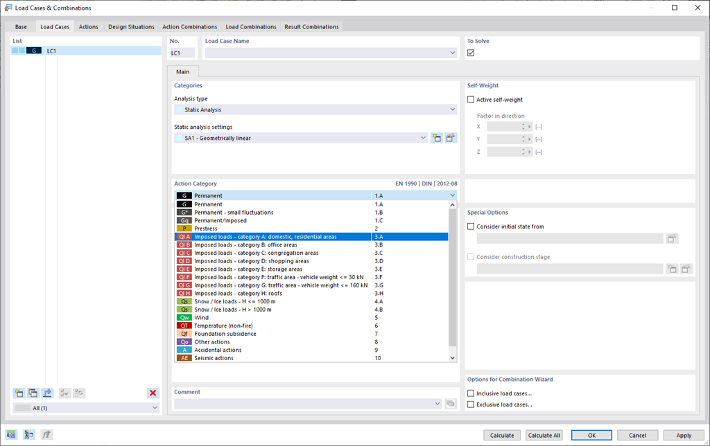
Load Cases and Combinations
To ensure that your structures can cope with all loads, take a look at the "Load Cases and Combinations" dialog box. Here you can create and manage load cases. Furthermore, you can also generate action and load combinations as well as design situations here. You can assign the action categories of the selected standard to the individual load cases. If you have assigned several loads to an action category, they can act simultaneously or alternatively (for example, either wind from the left or wind from the right).
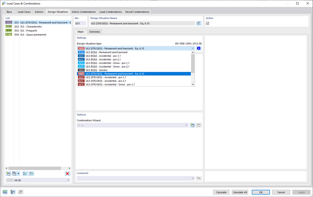
Combination Expressions
For the combination of actions, you have come to the right place. If you use them in the ultimate and the serviceability limit state, you can select various design situations according to the standard (for example, ULS (STR/GEO) - permanent/transient, SLS - quasi-permanent, and others). Optionally, you can also integrate imperfections in the combination and determine load cases that should not be combined with other load cases (for example, construction load for roof not combined with snow load).
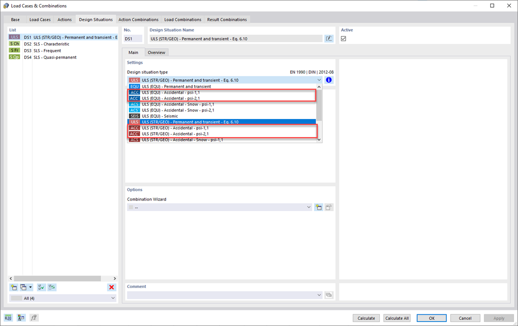
Accidental Design Situation
Do your structures also have to withstand unusual conditions? Then select the "accidental" design situation. Here, accidental actions such as earthquake, explosion loads, collisions, and many others, are considered automatically. Furthermore, when using German standards, you can select the "Accidental - Snow" design situation to consider the "North German Plain" automatically as well.
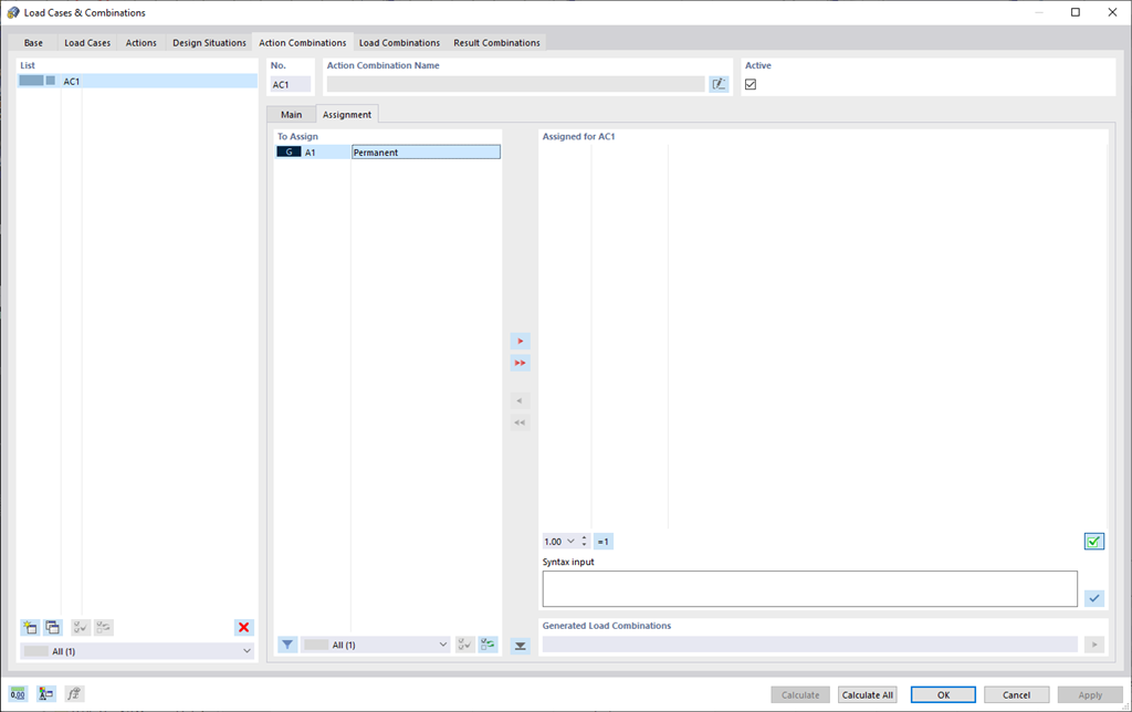
Action Combinations
Do you want to combine actions? Then use this feature. Here, the actions are automatically superimposed in accordance with combination expressions and then displayed as "action combinations". You can define which action combinations will eventually be used for the generation of load or result combinations. Based on the created action combinations, you can estimate how the combination expressions affect the number of combinations.
Load Combinations
RFEM 6 offers you a wide range of helpful and efficient functions for working with load combinations. You can add the load cases included in load combinations together and then calculate them in consideration of the corresponding factors (partial safety and combination factors, coefficients regarding consequence classes, and so on). Generate the load combinations automatically in compliance with the combination expressions of the standard. You can perform the calculation according to the linear static analysis, second-order analysis, or large deformation analysis, as well as for post-critical analysis. Optionally, you can define whether the internal forces should be related to the deformed or non-deformed structure.
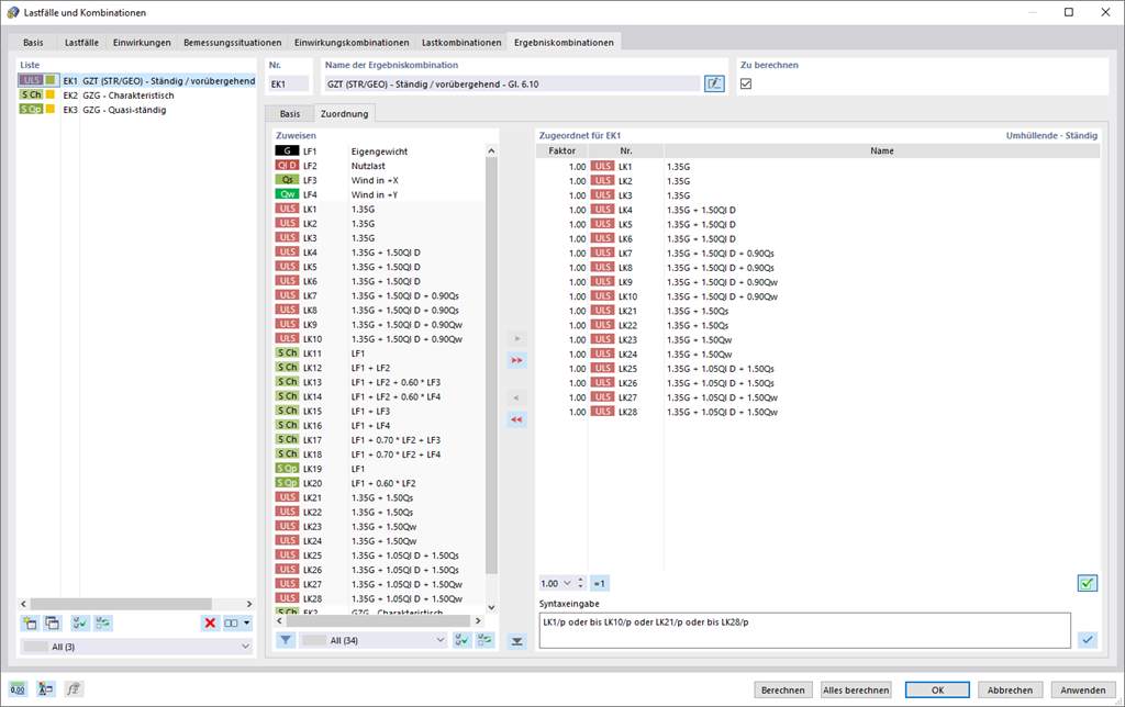
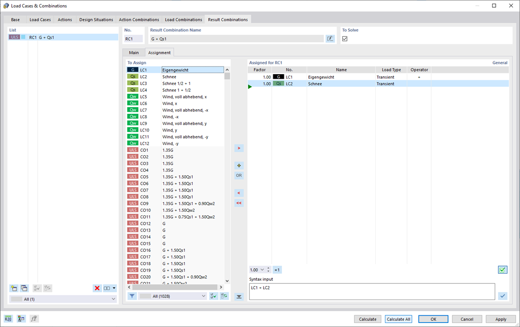
Result Combinations
Rely on RFEM 6 even in the case of result combinations. First, you can have the contained load cases calculated in the result combinations. Then, the results are superimposed by taking into account the corresponding factors. In the result combinations, you can superimpose the results of load cases, load combinations, and other result combinations. Internal forces are added together by default. However, you have the option of a square addition, which is relevant for dynamic analysis.
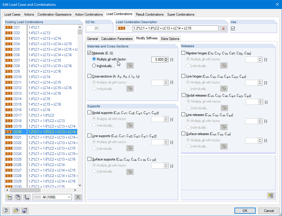
Modifying Stiffnesses / Considering Initial Deformations
Do not lose track of stiffnesses and initial deformations. In the individual load cases or combinations, you have the option to modify the stiffnesses of materials, cross-sections, nodal, line and surface supports, and member and line hinges for all or selected members. You can also consider initial deformations from other load cases or load combinations.
Calculate Your Price
The price is valid for United States. Prices are only valid for the software usage in United States. This quote is free of obligation. You can get exact prices after signing in. Please log on to your account at Dlubal Software to generate an updated quote.


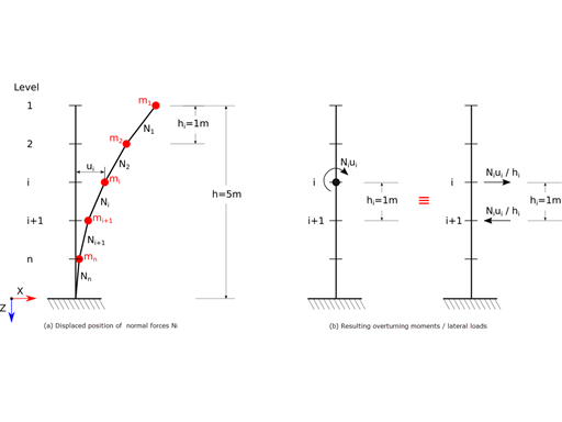
The coefficient θ is calculated as follows:$$\mathrm\theta\;=\;\frac{\displaystyle{\mathrm P}_\mathrm{tot}\;\cdot\;{\mathrm d}_\mathrm r}{{\mathrm V}_\mathrm{tot}\;\cdot\;\mathrm h}\;$$


In the "Edit Section" dialog box, you can display the buckling shapes of the Finite Strip Method (FSM) as a 3D graphic.

In RFEM 6 and RSTAB 9, you have the option to enter "Visual Objects" as guide objects. You can import the file formats 3ds, stl, and obj.
These objects allow you to create a better reference to the dimensions.
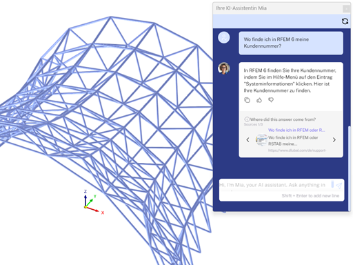
Mia is accessible in the programs and prevents the hassle of following up by email or phone.
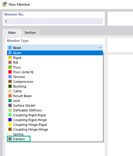
Using the "Dashpot" member type, you can define a damping coefficient, a spring constant, and a mass. This member type extends the possibilities within the Time History Analysis.
With regard to viscoelasticity, the "Dashpot" member type is similar to the Kelvin-Voigt model, which consists of the damping element and an elastic spring (both connected in parallel).


