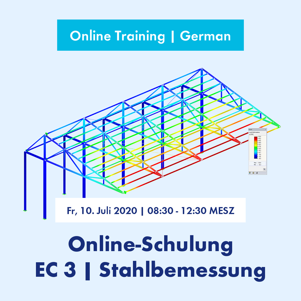
Eurocode 3 | Steel Design - Theory and Practical Examples According to DIN EN 1993-1-1
2020-07-10
8:30 AM - 12:30 PM CEST
German
Price
250.00 EUR incl. tax
We want to introduce Eurocode 3, Part 1‑1. The application of the add-on modules for steel structures, used for the standard-conforming design according to EC 3, will be explained using selected practical examples.
|
-
Introduction and application notes
Development of the EN 1993 series of standards Structure of the EN 1993 series of standards |
|
-
Basis of the calculation
Standards, combination rules, safety concept Design with limit states Material properties |
|
-
Conclusions
|
|
-
Ultimate limit state design checks according to DIN EN 1993-1-1
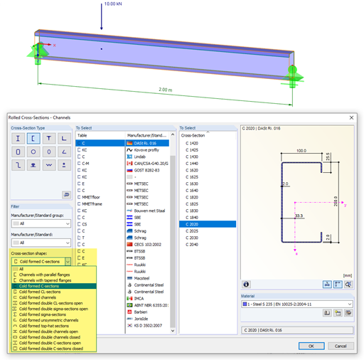
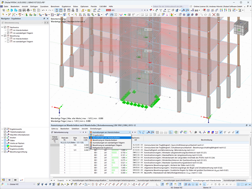
Cross-section classification Resistance of cross-sections Practical example with RFEM or RSTAB and RF-/STEEL EC3 |
|
-
Ultimate limit state design checks according to DIN EN 1993-1-1
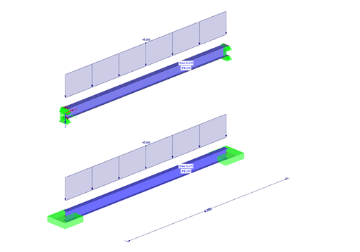
Explanation of structural component checks (stability)
Practical examples with RFEM or RSTAB and RF-/STEEL EC3 |
|
-
Serviceability and durability design checks according to EC 3
General
Limit states for building construction Practical example with RFEM or RSTAB and RF-/STEEL EC3 |
Notes
A reliable internet connection is required to participate. Basic knowledge of RFEM or RSTAB is also expected.
During the training, each participant can ask questions via chat at any time.
After the event, each participant will receive the models, video recordings, and materials presented in the training for download. This allows you to follow the entire training step by step again and try everything out in the program by yourself.
To take part in the online training, the participant will receive the login information in due time.


.png?mw=600&hash=49b6a289915d28aa461360f7308b092631b1446e)


