
Question:
How can I smooth continuous boundary lines of membrane cuttings?
Answer:
The perimeter of membrane cutting patterns is described by boundary lines. These boundary lines can be modeled by
1.
Globally defined boundary lines of the assigned membrane surfaces, or
2.
Subsequently introduced cutting lines for dividing the blanks on the membrane surfaces.
In this case, the cutting patterns can only consist of a global line definition or the cutting lines applied subsequently, or mixtures of both types.
The global boundary lines are untouchable due to their fixed geometry description (arc, circle, spline, and so on), and are also implemented in the design of planar cutting patterns in this way.
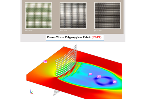
On the other hand, the subsequently applied cutting lines are based on the FE mesh of the surfaces assigned in the cutting line specification and have no influence on the mesh itself.
Cutting units encircled by boundary lines and cutting lines take over the FE mesh of the assigned surfaces for flattening. Since the cutting lines run through the FE elements themselves, with no regard to the global mesh in the edge area, the edges of the original FE elements cannot be used to describe the cutting pattern limitation. In this case, the affected FE elements within the cutting line area are divided by the cutting lines.
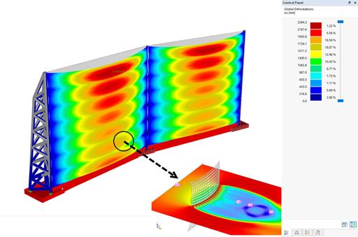
Depending on the orientation of the cutting line, the FE elements are cut in the middle or almost on the edge. Since the FE elements on the edge can cause some problems with the geometry, a certain tolerance limit has been entered for the decision. This limit controls the critical length ratio between the FE edge length specified by the cutting line and the original FE edge length. If the ratio is smaller than the given limiting value, the cutting line refers to the original FE node.
This fact may lead to an "Irritation" of the cutting line if the cutting lines are close to the FE element edges. This situation can be optimized by reducing the given tolerance limit.


.png?mw=350&hash=e3f5898d72f463e9b3e774659aabcb220466c522)

.jpg?mw=350&hash=196d91410dd36f58fcc8b0194f4577bb70cf53c3)


