Question:
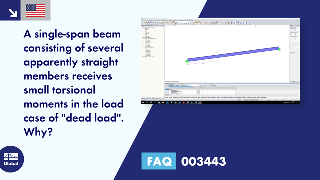
A single-span beam consisting of several apparently straight members receives small torsional moments in the load case of "dead load". Why?
Answer:
There is very likely an inaccuracy in the modeling, which has to be checked as follows:
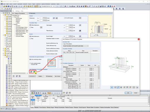
Set the view in the member direction, then zoom in.
Select all existing nodes that should lie on the same line: If the respective coordinates in the transverse direction do not correspond to the member axis, the corresponding field of the coordinate is empty and there is a deviation.


.png?mw=600&hash=49b6a289915d28aa461360f7308b092631b1446e)
