
Question:
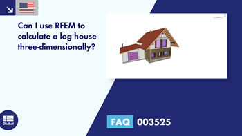
Can I use RFEM to calculate a log house three-dimensionally?
Answer:
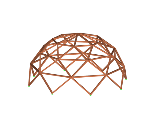
For many users, the very realistic display of a building in construction programs raises the desire to carry out the structural analysis of the building with the same complex spatial model.
Again and again, we are approached about the design of log houses. Unfortunately, this attractive construction method is relatively complex for three-dimensional analysis. In dimensioning, there are some critical questions that cannot be answered.
1.
Which sorting class is the timber subject to? In a log house, unsorted damp wood is often used.
2.
How is the contact between the timber types controlled? Diamond notch, connection with moving timbers, and so on?
3.
Have mullions been installed? What type of timber, and how are the beams supported horizontally?
4.
What dimensions does the timber have? In a log structure, a grown trunk can often be integrated. These trunks do not have uniform dimensions, as nature cannot be put into a grid.
5.
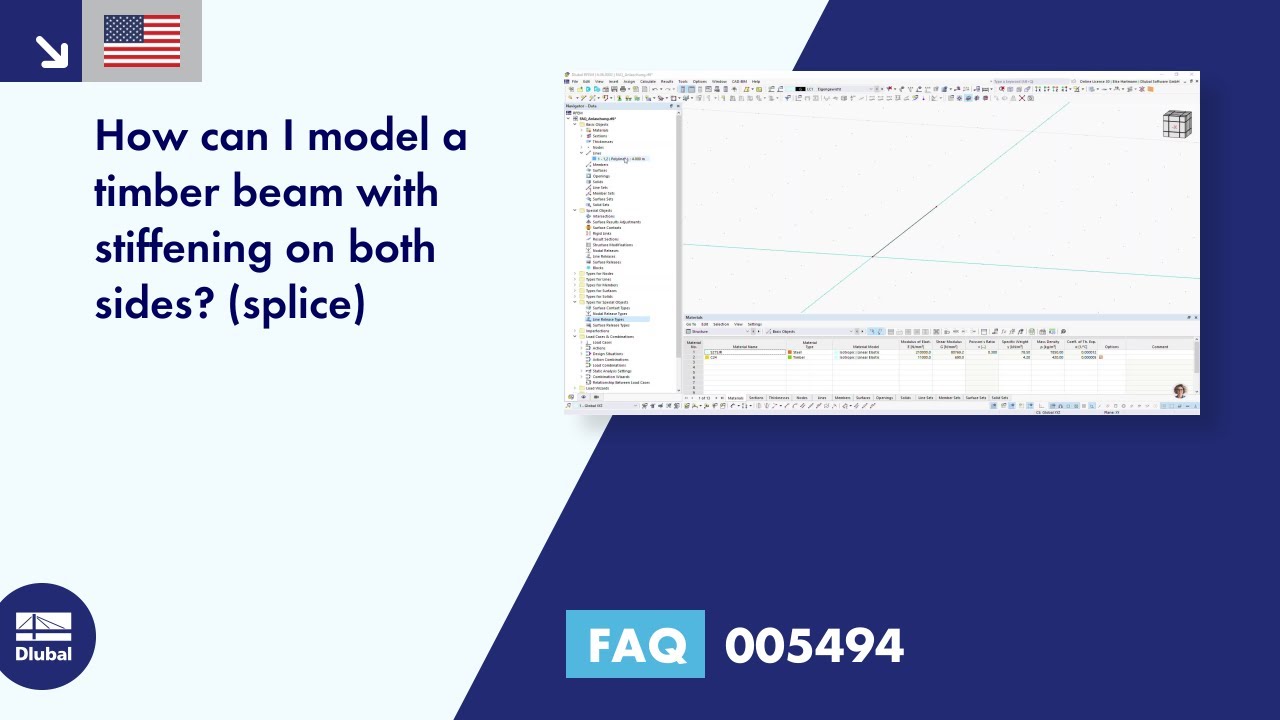
How is it possible to consider the contact between two timber layers?
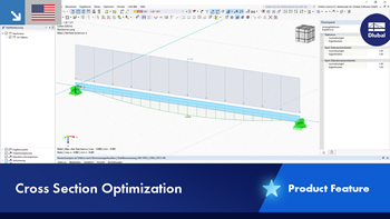
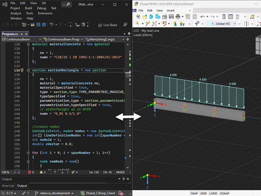
Furthermore, due to their high settlement of more than 15 cm per floor, logs are commonly used to construct houses with a maximum of 2 full floors. Thus, the occurring forces are within a manageable framework and can be determined sufficiently precisely with the structural analysis methods for members in 2D structures. In RFEM/RSTAB, there is an option to define round members in a tapered way for this purpose. Thus, the definition of 2D equivalent systems can be done much faster in RFEM/RSTAB.
Some information is found in the given literature source.


.png?mw=512&hash=4e74affa9ad0c7b703151c5085ac9b8e59171c23)


.jpg?mw=350&hash=8f312d6c75a747d88bf9d0f5b1038595900b96c1)


.png?mw=600&hash=49b6a289915d28aa461360f7308b092631b1446e)


