
Question:
I would like to carry out the flexural buckling design for timber components with imperfections and internal forces according to the second-order analysis. Is it sufficient to activate this in Details of the RF‑/TIMBER Pro add-on module or is it necessary to make additional settings?
Answer:
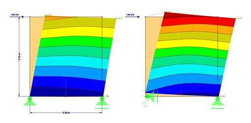
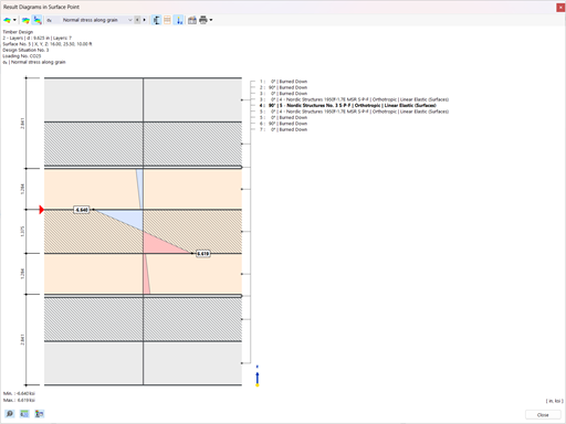
The setting in Image 01 only controls the effect on the design side. After activating this function, the buckling designs in the "Effective Lengths" window are deactivated. Thus, only the lateral-torsional buckling analysis is performed.
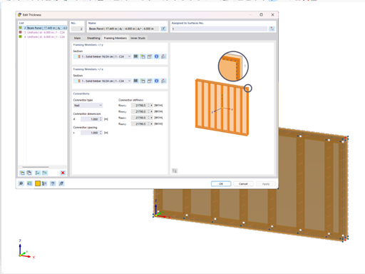
In order to calculate with the design values of stiffnesses, it is necessary to reduce them by the partial safety factor according to [1]. For this, select the highlighted option in the calculation parameters (see Image 02).
When using the automatic combinations for the standard EN 1990 + EN 1995, this setting is automatically activated in the combinations for ULS according to the second-order analysis. In the case of the combinations for the SLS and the combinations generated according to the linear static analysis, this option is automatically deactivated. However, the combinations are only assigned automatically using the method of analysis in the "Combination Expressions" tab (see Image 03).
If you want to calculate the component stiffnesses with the 5% quantile value of the stiffness parameters divided by the partial safety factor, you have to additionally activate the "Modify stiffnesses" option in the calculation parameters and modify the stiffnesses manually.


.png?mw=512&hash=4e74affa9ad0c7b703151c5085ac9b8e59171c23)


.jpg?mw=350&hash=8f312d6c75a747d88bf9d0f5b1038595900b96c1)


