
Question:
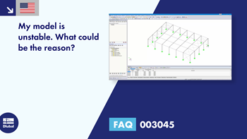
My model is unstable. What could be the reason?
Answer:
A calculation break‑off due to an unstable system can have different reasons. On one hand, it can indicate a "real" instability due to overloading the structural system; on the other hand, modeling inaccuracies may also be responsible for this error message. In the following text, you can find a possible procedure for finding the cause of the instability.
1. Check of Modeling
First, you should check if the modeling of the structural system is correct. We recommend using the model check tools provided by RFEM/RSTAB (Tools → Model Check). For example, these options allow you to find identical nodes and overlapping members, so you can delete them, if necessary.
Furthermore, you can calculate the structure subjected to pure dead load in a load case according to the linear static analysis, for example. If results are displayed subsequently, the structure regarding the modeling is stable. If this is not the case, the most common causes are listed below (see also the "Model Check" video under "Downloads"):
Incorrect Definition of Supports / Lack of Supports
This can lead to instabilities, as the structure is not supported in all directions. Therefore, the support conditions must be in equilibrium with the structural system as well as with the external boundary conditions. Statically underdetermined systems can also lead to calculation aborts due to a lack of boundary conditions.
Torsion of Members About Their Own Axes
If members rotate about their own axes - that is, a member is not supported about its own axis - this can lead to instabilities. This is often caused by the settings of member hinges. Thus, it may happen that the torsional releases are entered at both the start node and the end node. However, you should pay attention to the warning that appears when starting the calculation.
Missing Connection of Members
In the case of large and complex models in particular, it may quickly happen that some members are not connected to each other, thus they "float in the air". Also, if you forget about crossing members that should intersect with each other, this can lead to instabilities as well. A solution provides the model check of "Crossing Unconnected Members", which searches for members that cross each other, but do not have a common node at the intersection point.
No common node
The nodes seem to be at the same location, but on closer inspection, they deviate slightly from each other. This is often caused by CAD imports, and you can correct it using the model check.
Formation of Hinge Chain
Too many member end hinges on a node can cause a hinge chain that leads to a calculation abort. For each node, only n‑1 hinges with the same degree of freedom relative to the global coordinate system may be defined, where "n" is the number of connected members. The same applies to line releases.
2. Check of Stiffening
If the stiffening is missing, it may also lead to calculation aborts due to instabilities. Therefore, you should always check whether the structure is stiffened sufficiently in all directions.
3. Numerical Problems
An example of this is shown in Image 08. It is a hinged frame that is stiffened by tension members. Because of the column contractions due to vertical loads, the tension members receive small compressive forces in the first calculation step. They are removed from the structure (since only tension can be absorbed). In the second calculation step, the model is unstable without these tension members. There are several ways to solve this problem. You can apply a prestress (member load) to the tension members in order to "eliminate" the small compressive forces, assign small stiffness to the members, or remove the members one by one in the calculation (see Image 08).
4. Detecting Causes of Instability
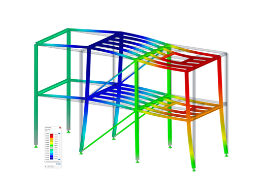
Automatic Model Check with Graphical Result Display
The RF-STABILITY (RFEM) add-on module can help you to obtain the graphical display of the instability cause. Select the "Calculate eigenvector for unstable model…" (see Image 09), and it is possible to calculate the unstable structure. The eigenvalue analysis is performed on the basis of the structural data so that the instability of the affected structural component is displayed graphically as a result.
Critical Load Problem
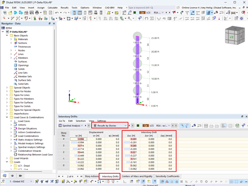
If load cases or load combinations can be calculated according to the linear static analysis and the calculation does not stop until the second-order analysis, there is a stability problem (critical load factor less than 1.00). The critical load factor indicates the factor by which the loading must be multiplied in order for the model to become unstable ...


.png?mw=600&hash=49b6a289915d28aa461360f7308b092631b1446e)


