Question:
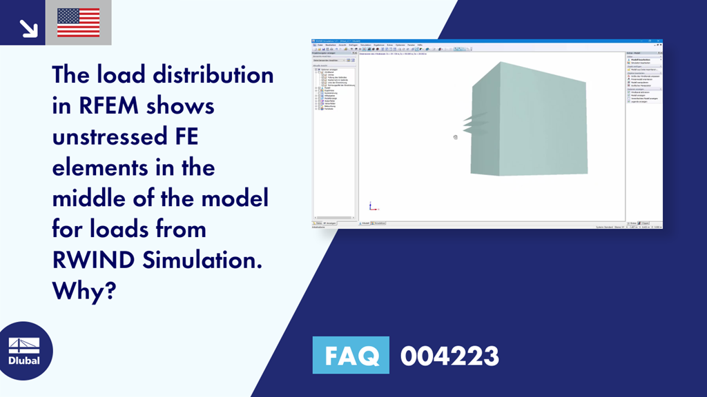
The load distribution in RFEM shows unstressed FE elements in the middle of the model for loads from RWIND Simulation. What is the reason?
Answer:
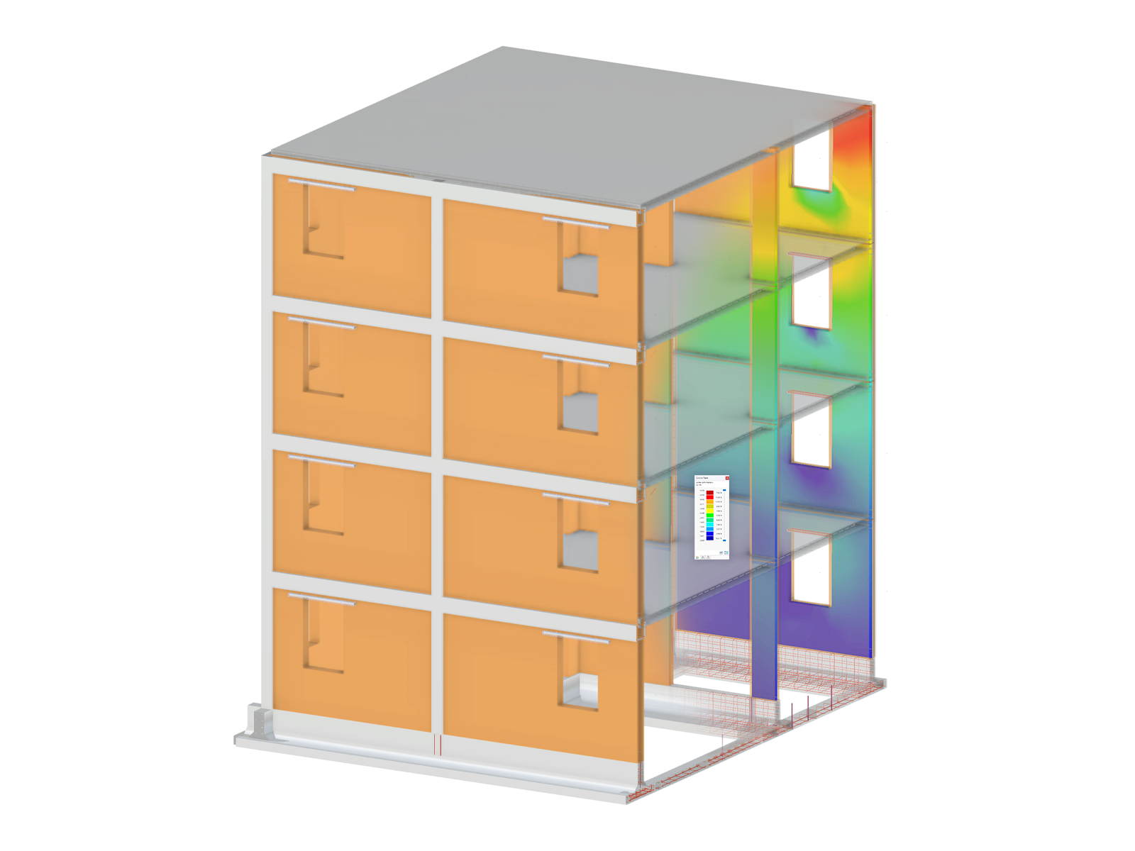
No load distribution is displayed between the external facade elements in the example shown in Image 01. The unstressed cells are not displayed according to the color scale for the load distribution, but remain empty. Thus, the value on these elements is 0. This has the advantage that it is recognized immediately that the FE elements are not subjected to a load.
The cause of the problem can be visualized directly in RWIND Simulation. By default, the calculations are based on a simplified model there. Depending on the setting, the shell of the model can be refined or coarsened. An FE mesh is placed over the structure, and depending on the level of detail, this FE mesh clings to the model. Image 02 shows what will happen if the level of detail is too small. The surfaces standing on the facade are not displayed well enough and no wind flows between the cantilevered surfaces in the simulation, which is why these internal surfaces are not subjected to any wind pressure.
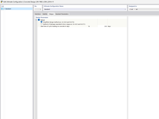
The level of detail can be adjusted in RWIND Simulation via "Edit Model" or directly in RFEM in the settings for the wind load simulation (see Image 03). Optionally, the simplified model can also be deactivated completely in RWIND Simulation.
In the case of a higher level of detail (corresponds to a finer FE mesh), the cantilevered surfaces are displayed cleanly and the FE elements are stressed accordingly (see Image 04 and Image 05).


.png?mw=600&hash=49b6a289915d28aa461360f7308b092631b1446e)


