
Topic:
Modeling and Design of Pinned End Plate Connection
Annotation:
RFEM offers the following possibilities to design a pinned end plate connection. Firstly, there is the possibility in RF-JOINTS Steel - Pinned to enter the corresponding parameters quickly and easily to receive a documented analysis including graphics. It is also possible to model such a connection individually in RFEM and then to evaluate or manually design the results. In the following example, the particularities of this modeling will be explained and the shear forces of the bolts will be compared to the corresponding results from RF-JOINTS Steel - Pinned.
Description:
System
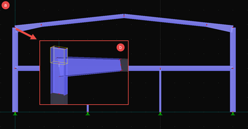
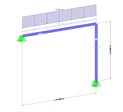
The entire structure is a simply supported half-frame, consisting of a 6 m long IPE-160 beam and a 4 m long IPE-200 column. The beam is connected with a welded, 5 mm thick end plate by bolts 4 x M12 to the column web.
The loading of the structure is the self-weight as well as a distributed load of 8 kN/m oriented in positive Z-direction (Figure 01).
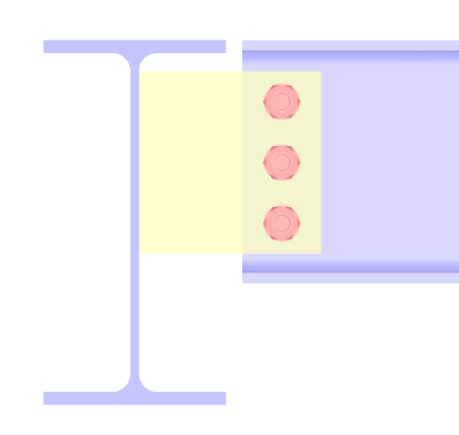
The end plate has the dimensions of w/h = 82/160 mm. The edge distances of the bolts amount to e1/e2 = 44/20.5 mm (Figure 02).
Option 1: Design of Connection with RF-JOINTS Steel - Pinned
After having modeled the structure in RFEM, including load case and loading, the RF-JOINTS Steel - Pinned add-on module can be opened. The corresponding input data can then be defined in the add-on module so that the design of this connection can be performed within a short period of time.
In this example, the carrying capacity of bolts in shear is the governing design (ratio 47 %, Figure 03). The maximum existing shear force Fn,Ed of a single bolt amounts to 6.12 kN.
Option 2: Modeling of Connection in RFEM
The alternative modeling of the connection in RFEM takes place in the following steps:
Copy of the model to be on the safe side.
Definition of the member eccentricity at the beam (half height of the beam in Z-direction, end plate thickness + half thickness of the column web in Y direction, only at the end of the connection, see Figure 04).
Right-click on Members → "Generate Surfaces from Member".
Deletion of nodal support, definition of hinged line supports at the bottom edge of the girder flange and at the end of the column web (see Figure 05).
Deletion of member load (8 kN/m) and conversion to surface load (97.6 kN/m2 on the girder flange).
Connection:
Modeling of end plate as solid element (cuboid, see Figure 06).
Insertion of the bolt holes with openings (see this article).
Copy of solid end plate to the end of the girder. Please note: End plate should have no contact to the surface of the column web due to the pinned joint, the force transmission is only carried out by the bolts (see Figure 07).
Copy of the openings of the end plate (bolt holes) to the surface of the column web.
To check if really no contact is present between end plate and surface of the column web, the calculation can be started at this point. A message about instability should appear.
The four bolts can be modeled each as cylindrical solid, consisting of circular and quadrangle surfaces.
In order to receive member internal forces for the bolts, it is necessary to place a result beam in the middle of each bolt (see Figure 08). In this example, a round steel with a diameter of 12 mm will be used as cross-section. More information about Result Beams is available in our Knowledge Base.
The calculation results in a maximum shear force within a bolt of Vz = 6.69 kN (see Figure 09).
Conclusion
The results from the main program RFEM and the RF-JOINTS Steel - Pinned add-on module are relatively close and are therefore comparable. In this example, it becomes apparent that there are many possibilities for modeling in RFEM. Compared to the fast design in the RF-JOINTS Steel - Pinned add-on module, the effort is, however, relatively high when modeling is performed manually so that the user has to decide individually which option of design is used.
More Videos:
► KB 001516 | Modeling and Design of Pinned End Plate Connection https://www.youtube.com/watch?v=lwDeOPxL2rw


.png?mw=600&hash=49b6a289915d28aa461360f7308b092631b1446e)


