Question:
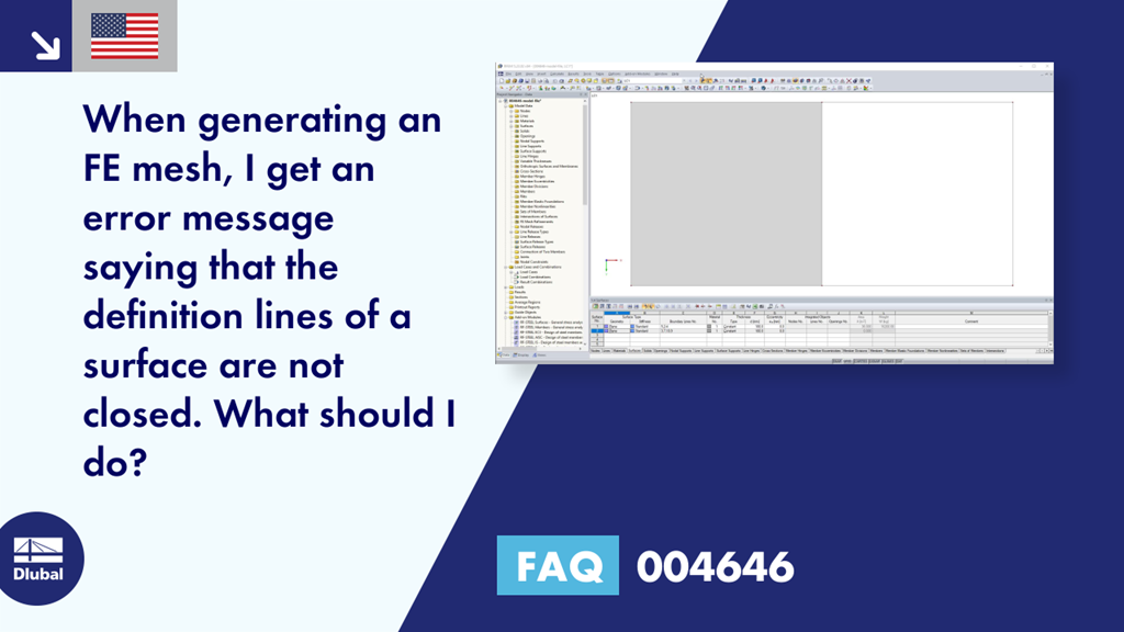
When generating an FE mesh, I get an error message saying that the definition lines of a surface are not closed. What should I do?
Answer:
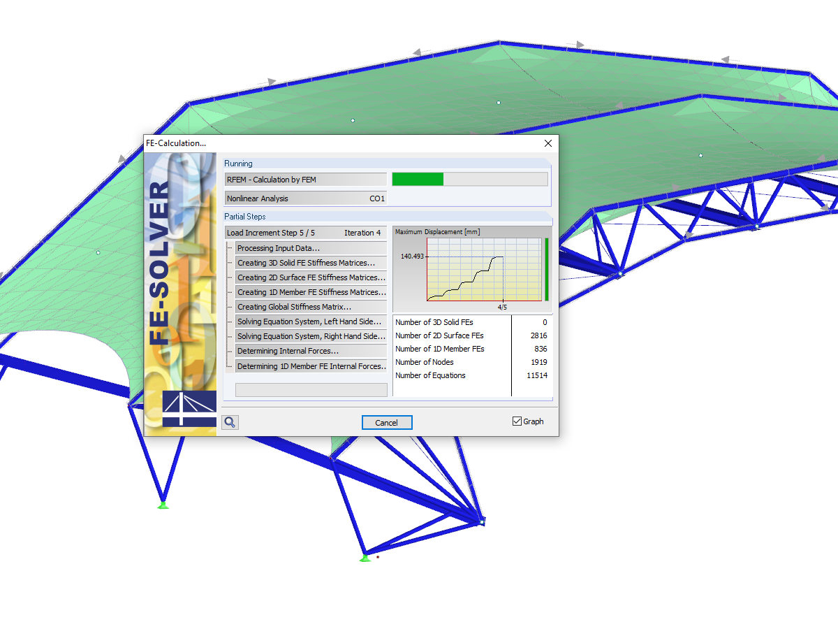
The boundary lines of a surface must form a closed continuous line. Otherwise, the error message shown in Image 01 appears.
The error message indicates the surface for which the definition lines are not closed. In our example, this is Surface 2 (marked in red in Image 01). In Project Navigator - Data, this surface is highlighted in red (Image 02).
The surface must be adjusted accordingly. In this case, it is necessary to add Line 8. This is also shown in the video.


.png?mw=512&hash=ea9bf0ab53a4fb0da5c4ed81d32d53360ab2820c)


.jpg?mw=350&hash=8f312d6c75a747d88bf9d0f5b1038595900b96c1)
