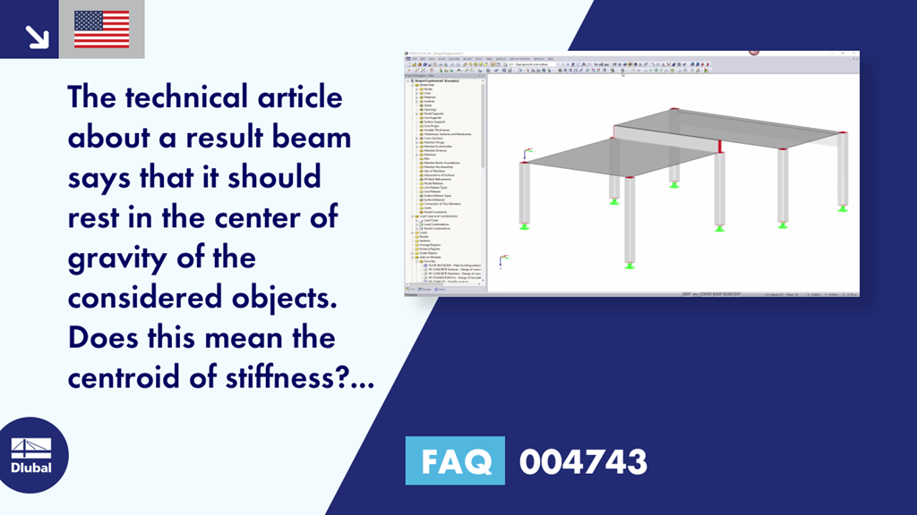
Home Support & Learning Learning Videos FAQ 004743 | The technical article about a result beam says that it should rest in the center of gravity of the considered objects. Does this mean the centroid of stiffness? Can I display it graphically with coordinates?
FAQ 004743 | The technical article about a result beam says that it should rest in the center of gravity of the considered objects. Does this mean the centroid of stiffness? Can I display it graphically with coordinates?
Video
Question
The technical article about a result beam says that it should rest in the center of gravity of the considered objects. Does this mean the centroid of stiffness? Can I display it graphically with coordinates?Answer
In this case, the center of gravity is the geometric center of gravity of the considered objects. This can be generated by the program: Select all relevant objects and then right-click one of these objects. In the shortcut menu, select the "Center of Gravity and Info..." feature.Keywords
Dlubal FAQ Result beam Center of gravity and info Frequently Asked Question FAQ about Dlubal Question and Answer about Dlubal
Links
Recommended Events
Eurocode 5 | Timber structures according to EN 1995-1-1
Online Training 03/17/2021 8:30 AM - 12:30 PM CET
Eurocode 3 | Steel structures according to DIN EN 1993-1-1
Online Training 03/18/2021 8:30 AM - 12:30 PM CET
Eurocode 3 | Steel structures according to DIN EN 1993-1-1
Online Training 05/06/2021 8:30 AM - 12:30 PM
Eurocode 2 | Concrete structures according to DIN EN 1992-1-1
Online Training 05/11/2021 8:30 AM - 12:30 PM
Eurocode 5 | Timber structures according to DIN EN 1995-1-1
Online Training 05/20/2021 8:30 AM - 12:30 PM
RFEM | Structural dynamics and earthquake design according to EC 8
Online Training 06/02/2021 8:30 AM - 12:30 PM
Videos
Models to Download
Knowledge Base Articles
New
Connection of Tables and Dialog Boxes
By double‑clicking the element numbers (first column) of the table, the according dialog box appears.
Screenshots
Product Features Articles
New
Increased Calculation Performance by Reducing the Nodal Degrees of Freedom
The number of degrees of freedom in a node is no longer a global calculation parameter in RFEM (6 degrees of freedom for each mesh node in 3D models, 7 degrees of freedom for the warping torsion analysis). Thus, each node is generally considered with a different number of degrees of freedom, which leads to a variable number of equations in the calculation.
This modification speeds up the calculation, especially for models where a significant reduction of the system could be achieved (e.g. trusses and membrane structures).
Frequently Asked Questions (FAQ)
- How can I create a curved or curved section?
- How can I change the colors of the selection and preselection?
- How are the signs to be interpreted for the release results of the line release and line hinges?
- Can I have generated member loads from surface loads act eccentrically on the member section by means of a plane?
- After calculating the add -on module RF-/DYNAM Pro - Equivalent Loads, the size of my file has increased significantly. The performance has deteriorated enormously. What could be the reason for this?
- Why are my imperfections displayed differently and can I adjust the display?
- What happens to the programs and add -on modules if the network license times out? And how can I increase the timeout?
- Why is it not possible to select a load case in the RF-/STEEL add-on module for design, although it is defined in RFEM/RSTAB?
- Why is the deflection of the reinforced concrete floor sometimes greater when selecting a larger basic reinforcement?
- I have a question about message no.47 in the RFEM program. What is the exact meaning of the word integrate? What is the resulting effect?
Customer Projects