Question:
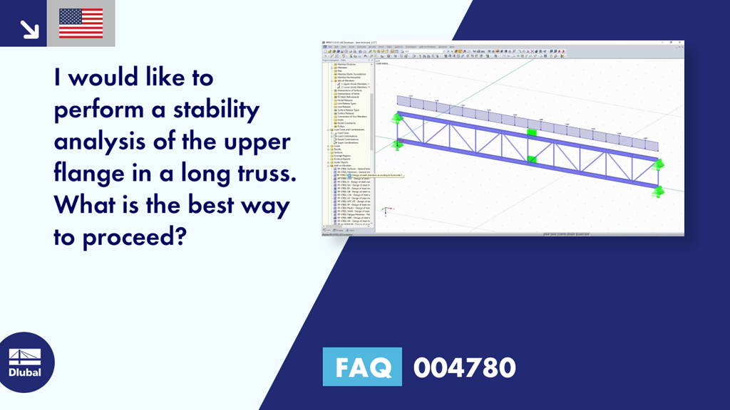
I would like to perform a stability analysis of the upper flange in a long truss. What is the best way to proceed?
Answer:
According to DIN EN 1993‑1‑1:2010‑12 [1], Annex BB.1.1, the buckling length may be used in the individual bracing under certain conditions. This means that it is not the set of members that may be used in this case, but the individual members with the effective length factors specified in the standard.
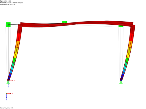
Since this approach only considers the local failure, it is necessary to analyze the global failure of the entire structure. For this design, the set of members must have the corresponding imperfection. Under certain conditions, the design can be performed on single members, depending on the model (for example, a tower), or the set of members must be analyzed for a failure from the plane (the truss), as in the attached example.


.png?mw=600&hash=49b6a289915d28aa461360f7308b092631b1446e)


