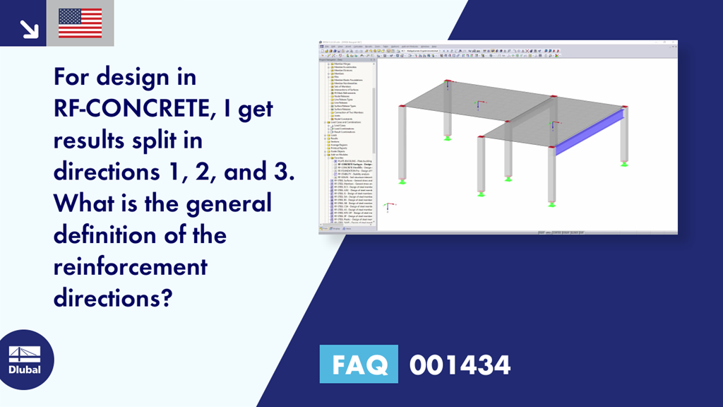
Question:
For design in RF‑CONCRETE, I get results split in directions 1, 2, and 3. What is the general definition of the reinforcement directions?
Answer:
The position of the reinforcement is defined in RFEM as follows:
1.) Directions 1, 2, and 3
Directions 1, 2, and 3 for the results of RF‑CONCRETE Surfaces are the reinforcement directions. Directions 1 and 2 correspond to the directions of the local axes x and y. Direction 1 corresponds to the local x-axis, Direction 2 to the local y-axis (provided that no rotation angle has been defined for the reinforcement: n1 = x and n2 = y for phi1 = 0° and phi2 = 90°).
A rotation angle would then define Axis 3.
You can set the angle in Window 1.4 of RF‑CONCRETE Surfaces in the Reinforcement Layout tab.
For internal forces, designations 1 and 2 are the principal axis directions.
2.) Top/Bottom for Reinforcement (global Z-axis, bottom)
Since RFEM can also calculate and design three-dimensional structures, the description for reinforcement layers must be oriented to the local surface axis systems.
Top means on the side of the surface opposite the positive local z-axis direction. Accordingly, the bottom position in the + z-direction is defined by the local coordinate system. For better differentiation from the global coordinate system (X, Y, Z), it is identified with lowercase letters.
The x- and y-axes lie on the surface; the z-axis is perpendicular to the surface. You can display the local axis system as follows:
- Activate the Display navigator on the left side of the screen (it is possible to set all display properties in a tree-like structure)
Open the branch "Model" → "Surfaces" and activate the check box in front of the "Surface Axis Systems x, y, z" entry.