
Question:
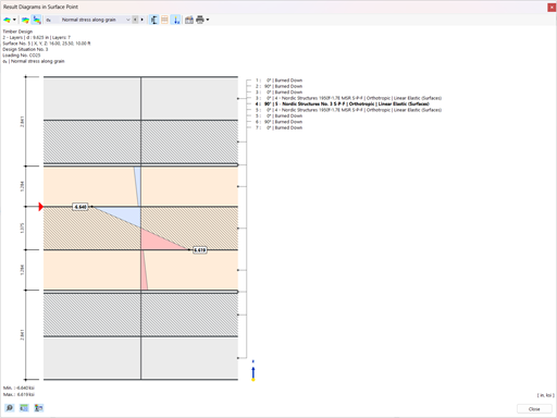
Is it possible to display more values for the stress distribution over the layers in RF‑LAMINATE?
Answer:
In the graphic, this is not possible for reasons of clarity. However, the RF‑LAMINATE add-on module also allows you to display the stresses in all points. This is deactivated by default because it quickly produces a huge amount of data for large structures.
If you also filter by the stress component that interests you, the results in the table quickly become clear, and you can easily evaluate the distribution of stresses at a point using the layers there.


.png?mw=350&hash=117ad3f33c60ab58cde72c606f62ba73be0be9f3)

Dlubal_KohlA_]_LI.jpg?mw=350&hash=3003b9f714a1214f2653bd7cb04e79f76b1a12ed)


.png?mw=350&hash=22d4cc5696e7961e8d9ee2a7db1c2f74839b0477)


.png?mw=512&hash=4e74affa9ad0c7b703151c5085ac9b8e59171c23)


.jpg?mw=350&hash=8f312d6c75a747d88bf9d0f5b1038595900b96c1)


