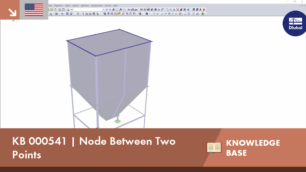
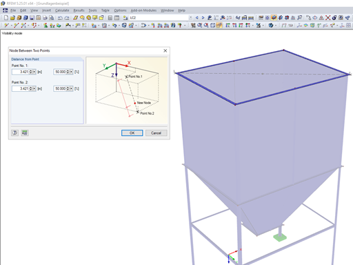
We provide hints and tips to help you get started with the basic program RFEM.
KB 000541 | node between two points
Video
First Steps with RFEM
Description
If you wanted to determine the center of a rectangle, it was previously necessary to construct a line from one corner point to the opposite one. By dividing this line, you obtain the centroid. In RFEM 5 and RSTAB 8, you now have the possibility to create a node between two points. Thus, it is sufficient to select the corner points, and then you can determine the distance in absolute or relative values.
Keywords
Dlubal Knowledge Base nodes Centroid Point Dlubal KB Knowledge Base Technical Contribution
Links
Contact us
Do you have any questions about our products or need advice on selecting the products needed for your projects?
Contact us via our free e-mail, chat, or forum support or find various suggested solutions and useful tips on our FAQ page.
Recommended Events
Timber Beam and Surface Structures | Part 1: Modeling, Load Input, Combinatorics
Webinar 05/04/2021 2:00 PM - 3:00 PM CEST
Eurocode 3 | Steel structures according to DIN EN 1993-1-1
Online Training 05/06/2021 8:30 AM - 12:30 PM CEST
Eurocode 2 | Concrete structures according to DIN EN 1992-1-1
Online Training 05/12/2021 8:30 AM - 12:30 PM CEST
Eurocode 5 | Timber structures according to DIN EN 1995-1-1
Online Training 05/20/2021 8:30 AM - 12:30 PM CEST
RFEM | Structural dynamics and earthquake design according to EC 8
Online Training 06/02/2021 8:30 AM - 12:30 PM CEST
Videos
Models to Download
Knowledge Base Articles

New
Placing Node Between Two Points
If you wanted to determine the center of a rectangle, it was previously necessary to construct a line from one corner point to the opposite one. By dividing this line, you obtain the centroid. In RFEM 5 and RSTAB 8, you now have the possibility to create a node between two points. Thus, it is sufficient to select the corner points, and then you can determine the distance in absolute or relative values.
Screenshots
Product Features Articles

SHAPE-THIN determines the effective cross-sections according to EN 1993-1-3 and EN 1993-1-5 for cold-formed sections. You can optionally check the geometric conditions for the applicability of the standard specified in EN 1993‑1‑3, Section 5.2.
The effects of local plate buckling are considered according to the method of reduced widths and the possible buckling of stiffeners (instability) is considered for stiffened sections according to EN 1993-1-3, Section 5.5.
As an option, you can perform an iterative calculation to optimize the effective cross-section.
You can display the effective cross-sections graphically.
Read more about designing cold-formed sections with SHAPE-THIN and RF-/STEEL Cold-Formed Sections in this technical article: Design of a Thin-Walled, Cold-Formed C-Section According to EN 1993-1-3.
Frequently Asked Questions (FAQ)
- In connection with the calculation according to the large deformation analysis, I get significantly smaller deformations than for the calculation according to the linear static or second-order analysis. How is this possible?
- How is it possible to consider the real cross-section geometry of member elements in RWIND Simulation?
- My aim is to mesh a circular hole plate in a mapped way. Is such a meshing possible in RFEM?
-
Why are my steel members not being designed for stability in RF-STEEL AISC?
- My section is classified as Class 4 and non-designable in RF-/STEEL CSA. However, my manual calculation shows a different class. Why the difference?
- Can the properties, such as B. the cross -section or the surface thickness as well as the material of a surface of an existing element for a new element?
- I have defined temperature loads, strain loads, or a precamber. As soon as I modify stiffnesses, the deformations are no longer plausible.
- I am trying to manually check the deformations from the CRANEWAY add-on module. However, I obtain great deviations. How to explain the differences?
- What should be considered when using a failure of columns under tension in the RF‑/DYNAM Pro – Equivalent Loads add-on module?
- Why is there no stability analysis displayed in the results despite the activation of the stability analysis in RF‑/STEEL EC3?
Customer Projects