
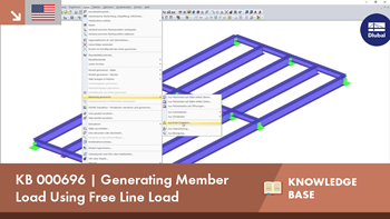
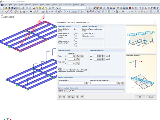
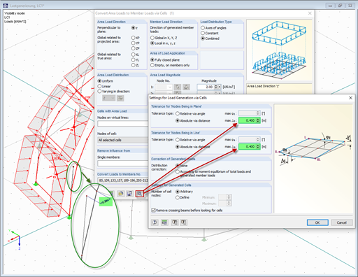
Not all structural elements of a real building are included in a structural model. As an example, we can look at a pipe that runs along a steel girder frame. The load of the beam would be transferred as concentrated loads on the beam below. To avoid having to manually divide the corresponding parts of the load, you can find the "From free line load" load generator under "Tools" → "Generate loads."


.png?mw=350&hash=b2324c4db119938012b5490afaa56e9aa826cdcc)


.png?mw=600&hash=49b6a289915d28aa461360f7308b092631b1446e)


