Free
Pipeline design - RF-PIPING series modules (pl)
Do you have any questions?


Length: 00:00:38 min
Length: 00:00:31 min

Length: 00:00:34 min
Length: 00:00:00 min
Length: 00:01:00 min
Length: 01:06:55 min
Length: 01:06:05 min


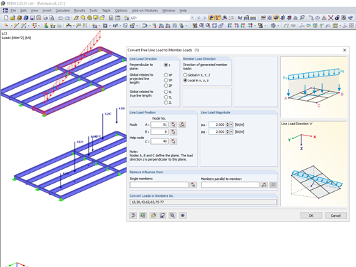
Not all structural elements of a real building are included in a structural model. As an example, we can look at a pipe that runs along a steel girder frame.
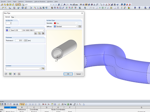
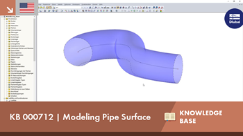
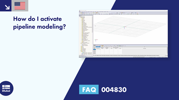
It may become necessary to analyze pipe cross‑sections as surface models in plant engineering in particular, but also when analyzing details of structural systems. For this purpose, RFEM offers the option to create pipe cross‑sections automatically by means of a line.
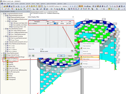
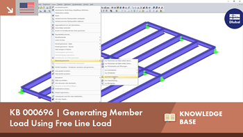
In many cases, it is necessary to filter the results for the display of values on surfaces so as not to show all the numbers. In displaying the reinforcement arrangement, you can, for example, hide values that are below the already used basic reinforcement.
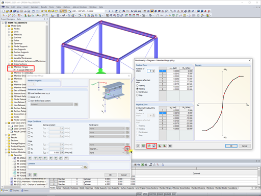
In RFEM 5 and RSTAB 8, it is possible to assign nonlinearities to member hinges. In addition to the nonlinearities "Fixed if" and "Partial activity", you can select "Diagram". If you select the "Diagram" option, you have to specify the according settings for the activity of the member hinge. For the individual definition points, it is necessary to specify the abscissa and ordinate values (deformations or rotations and the according internal forces) that define the hinge.


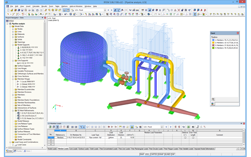
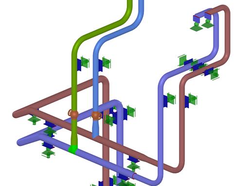
After activating the RF‑PIPING add‑on module, a new toolbar is available in RFEM and the project navigator and tables are extended. The piping system is now modeled in the same way as the members. Pipe bends are defined simultaneously by tangents (straight pipe sections) and radius. Thus, it is easy to subsequently change bend parameters.
It is also possible to extend the piping subsequently by defining special components (expansion joints, valves, and others). The implemented libraries of structural components facilitate the definition.
Continuous pipe sections are defined as sets of piping systems.
For piping loads, member loads are assigned to the respective load cases. The combination of loads is included in piping load combinations and result combinations.
After the calculation, you can display deformations, member internal forces, and support forces graphically or in tables.
Pipe stress analysis according to standards can then be performed in the RF‑PIPING Design add‑on module. You only need to select the relevant sets of piping systems and load situations.
- Response spectra in accordance with different standards
- The following standards are implemented:
-
 EN 1998-1:2010 + A1:2013 (European Union)
 -
 DIN 4149:1981-04 (Germany)
 -
DIN 4149:2005-04 (Germany)
-
 IBC 2000 (USA)
 -
IBC 2009-ASCE/SEI 7-05 (USA)
-
IBC 2012/15 - ASCE/SEI 7-10 (USA)
-
IBC 2018 - ASCE/SEI 7-16 (USA)
-
 ÖNORM B 4015:2007-02 (Austria)
 -
 NTC 2018 (Italy)
 -
 NCSE-02 (Spain)
 -
 SIA 261/1:2003 (Switzerland)
 -
SIA 261/1:2014 (Switzerland)
-
SIA 261/1: 2020 (Switzerland)
-
 O.G. 23089 + OG 23390 (Turkey)
 -
 SANS 10160-4 2010 (South Africa)
 -
 SBC 301:2007 (Saudi Arabia)
 -
 GB 50011 - 2001 (China)
 -
GB 50011 - 2010 (China)
-
 NBC 2015 (Canada)
 -
 DTR BC 2-48 (Algeria)
 -
DTR RPA99 (Algeria)
-
 CFE Sismo 08 (Mexico)
 -
 CIRSOC 103 (Argentina)
 -
 NSR - 10 (Colombia)
 -
 IS 1893:2002 (India)
 -
 AS1170.4 (Australia)
 -
 NCh 433 1996 (Chile)
-
- The following National Annexes according to EN 1998‑1 are available:
-
DIN EN 1998-1/NA:2011-01 (Germany)
-
ÖNORM EN 1991-1-1:2011-09 (Austria)
-
 NBN - ENV 1998-1-1: 2002 NAD-E/N/F (Belgium)
 -
 ČSN EN 1998-1/NA:2007 (Czech Republic)
 -
 NF EN 1998-1-1/NA:2014-09 (France)
 -
UNI-EN 1991-1-1/NA:2007 (Italy)
-
 NP EN 1998-1/NA:2009 (Portugal)
 -
 SR EN 1998-1/NA:2004 (Romania)
 -
 STN EN 1998-1/NA:2008 (Slovakia)
 -
 SIST EN 1998-1:2005/A101:2006 (Slovenia)
 -
 CYS EN 1998-1/NA:2004 (Cyprus)
 -
 NA to BS EN 1998-1:2004:2008 (United Kingdom)
 - NS-EN 1998-1:2004 + A1:2013/NA:2014 (Norway)
-
- User-defined response spectra
- Direction-relative response spectrum approach
- Relevant mode shapes for the response spectrum can be selected manually or automatically (5% rule from EC 8 can be applied)
- Generated equivalent static loads are exported to load cases, separately for each modal contribution and separately for each direction
- Result combinations by modal superposition (SRSS and CQC rule) and direction superposition (SRSS or 100% / 30% rule)
- Signed results based on the dominant eigenmode can be displayed
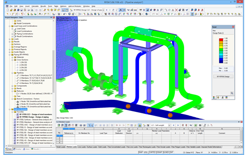
After modeling piping systems in RFEM using RF‑PIPING and defining loads as well as load and result combinations, you can carry out pipe stress analysis in the RF‑PIPING Design add‑on module.
You can select all or only some pipelines and loads, load or result combinations for piping design. The material library provides various materials according to EN 13480‑3, ASME B31.1‑2012, and ASME B31.3‑2012 standards.
After the calculation, the results are displayed in clearly arranged windows; for example, by cross‑section, by pipeline, or by members. You can also display the design ratio graphically on the entire model in RFEM. This way, you can quickly recognize critical or oversized areas of the cross-section.
In addition to the input and result data, including design details displayed in tables, you can add all graphics into the printout report. This way, comprehensible and clearly arranged documentation is guaranteed. You can select the report contents and extent specifically for the individual designs.
- Design according to EN 13480-3, ASME B31.1-2012, and ASME B31.3-2012
- Check of the minimum required wall thickness of the pipes, taking into account manufacturing allowances, corrosion, and welding factor
- Analysis of stresses due to sustained loads, sustained and occasional loads as well as due to thermal expansion
- Result documentation with tables and graphics in the RFEM printout report
I design pipelines using the RF-PIPING Design add-on module. I have created a new prestress load case and loaded the piping with longitudinal displacement.
Is it possible to add this new load case to combinations that are generated automatically?
Is it possible to add this new load case to combinations that are generated automatically?
Is it possible to automatically generate zones in RWIND 2?
How can I create a response spectrum according to ASCE 7‑22?
I have display problems in RFEM 6, RSTAB 9, and RSECTION 1, or the program crashes immediately after starting it. What options do I have to improve this?
How can I adjust font sizes in RFEM 6 and RSTAB 9 for a screen view and a printout report?
In the case of stairs with a complicated geometry, it is often difficult to design welds by using the analytical methods. How can I do this with RFEM?


.jpg?mw=350&hash=8f312d6c75a747d88bf9d0f5b1038595900b96c1)


Recommended Products for You
RFEM 5 | Piping Systems

Modeling piping systems
Price of First License
2,200.00 USD
RFEM 5 | Piping Systems

Piping design and pipe stress analysis
Price of First License
1,750.00 USD
RFEM 5 | Main Program RFEM

Structural engineering software for a finite element analysis (FEA) of planar and spatial structural systems consisting of plates, walls, shells, members (beams), solids, and contact elements
Price of First License
4,080.00 USD
RFEM 6 | Main Program RFEM 6

The new generation of 3D FEA software is used for the structural analysis of members, surfaces, and solids.
Price of First License
4,170.00 USD
RFEM 6 | Dynamic Analysis

The Modal Analysis add-on allows for the calculation of eigenvalues, natural frequencies, and natural periods for member, surface, and solid models.
Price of First License
1,210.00 USD
RFEM 6 | Dynamic Analysis

The Response Spectrum Analysis add-on performs seismic analysis using multi-modal response spectrum analysis. The spectra required for this can be created in compliance with the standards or can be user-defined. The equivalent static forces are generated from them. The add-on includes an extensive library of accelerograms from seismic zones that can be used to generate the response spectra.
Price of First License
1,390.00 USD
RFEM 6 | Dynamic Analysis

Using the Pushover Analysis add-on, you can analyze the seismic actions on a particular building, and thus assess whether the building can withstand an earthquake.
Price of First License
1,300.00 USD
RFEM 6 | Additional Analysis

The Time-Dependent Analysis (TDA) add-on allows you to consider the time-dependent material behavior of members. The long-term effects, such as creep, shrinkage, and aging, can influence the distribution of internal forces, depending on the structure.
Price of First License
1,030.00 USD
RFEM 6 | Design

The Concrete Design add-on allows for various design checks according to international standards. You can design members, surfaces, and columns, as well as perform punching and deformation analyses.
Price of First License
2,550.00 USD
RFEM 6 | Design

The Steel Design add-on performs the ultimate and serviceability limit state design checks of steel members according to various standards.
Price of First License
2,550.00 USD
RFEM 6 | Design

The Timber Design add-on performs the ultimate, serviceability, and fire resistance limit state design checks of timber members according to various standards.
Price of First License
1,930.00 USD
RFEM 6 | Design

The Masonry Design add-on for RFEM allows you to design masonry using the finite element method. It was developed as part of the research project titled DDMaS – Digitizing the Design of Masonry Structures. The material model represents the nonlinear behavior of the brick-mortar combination in the form of macro-modeling.
Price of First License
1,660.00 USD
RFEM 6 | Design

The Aluminum Design add-on performs the ultimate and serviceability limit state design checks of aluminum members according to various standards.
Price of First License
1,750.00 USD
RSTAB 9 | Main Program RSTAB 9

The modern 3D structural analysis and design program is suitable for the structural and dynamic analysis of beam structures as well as the design of concrete, steel, timber, and other materials.
Price of First License
2,910.00 USD
RSTAB 9 | Dynamic Analysis
The Modal Analysis add-on allows for the calculation of eigenvalues, natural frequencies, and natural periods for member, surface, and solid models.
Price of First License
1,210.00 USD
RSTAB 9 | Dynamic Analysis
The Response Spectrum Analysis add-on performs seismic analysis using the multi-modal response spectrum analysis. The spectra required for this can be created in compliance with the standards or can be user-defined. The equivalent static forces are generated from them. The add-on includes an extensive library of accelerograms from seismic zones that can be used to generate response spectra.
Price of First License
1,390.00 USD
RSTAB 9 | Dynamic Analysis
Earthquakes may have a significant impact on the deformation behavior of buildings. A pushover analysis allows you to analyze the deformation behavior of buildings and compare them with seismic actions. Using the Pushover Analysis add-on, you can analyze the seismic actions on a particular building, and thus assess whether the building can withstand the earthquake.
Price of First License
1,300.00 USD
RSTAB 9 | Design
Concrete Design add-on allows for various design checks of members and columns according to international standards.
Price of First License
2,550.00 USD
RSTAB 9 | Design
The Steel Design add-on performs the ultimate and serviceability limit state design checks of steel members according to various standards.
Price of First License
2,550.00 USD
RSTAB 9 | Design
The Timber Design add-on performs the ultimate, serviceability, and fire resistance limit state design checks of timber members according to various standards.
Price of First License
1,930.00 USD
RSTAB 9 | Design
The Aluminum Design add-on performs the ultimate and serviceability limit state design checks of aluminum members according to various standards.
Price of First License
1,750.00 USD