A calculation break‑off due to an unstable system can have different reasons. On one hand, it may indicate a real instability due to an overload of the system, but on the other hand, the error message may be caused by modeling errors. In the following text, you can find a possible procedure to find the cause of the instability.
First, you should check to see if the modeling of the structural system is correct. You can use the model checks (menu "Tools" → "Model Check") to find problems in the modeling.
Furthermore, you can calculate the model in a load case according to the linear static analysis under pure self-weight. If results are displayed subsequently, the structure regarding the modeling is stable. If this is not the case, the most common causes are listed below (see also Video 1):
- Supports are missing or have been defined incorrectly.
- Members can rotate about their own axes because the corresponding support is missing.
- Members are not connected to each other ("Tools" → "Model Check").
- Nodes apparently rest at the same location, but on closer inspection, they deviate from each other slightly (common cause in the case of CAD Import, "Tools" → "Model Check").
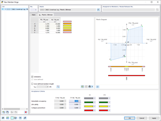
- Member end releases / line hinges cause a "hinge chain".
- The structure is insufficiently stiffened.
- Nonlinear structural elements (for example, tension members) fail.
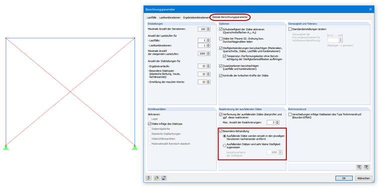
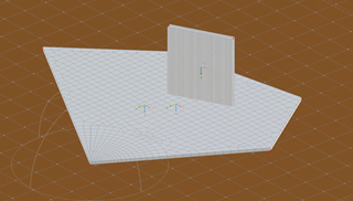
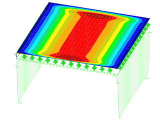
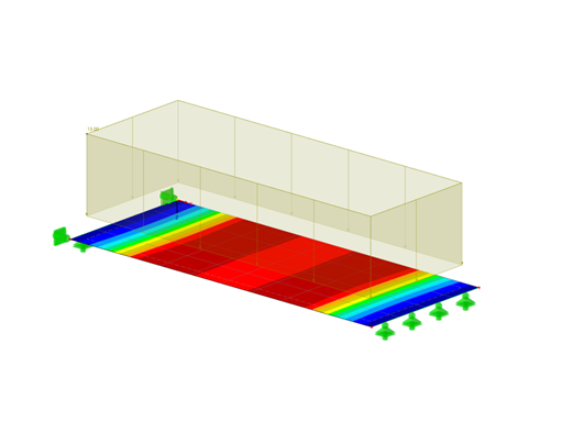
Image 02 shows an example of the last point. It is a hinged frame that is stiffened by tension members. Because of the column contractions due to vertical loads, the tension members receive small compressive forces in the first calculation step. They are removed from the structure (since only tension can be absorbed). In the second calculation step, the model is unstable without these tension members. There are several ways to solve this problem: You can apply a prestress (member load) to the tension members to "eliminate" the small compression forces, to assign a small stiffness to the members (see Image 02), or allow the members to be removed one by one in the calculation (see Image 02).
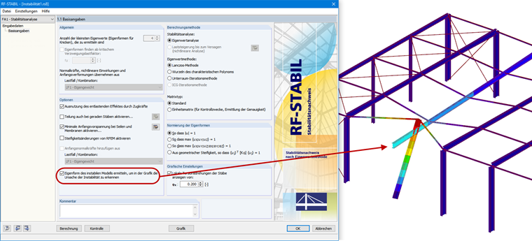
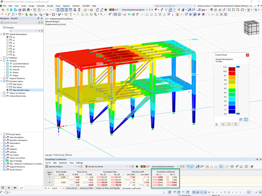
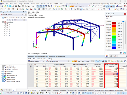
The RF-STABILITY add-on module (for RFEM 5) can help you to obtain the graphical display of the instability cause. The "Calculate eigenvector for unstable model..." option allows you to calculate unstable structural systems. In the graphic, you can usually recognize the structural component that leads to the instability.
If it is possible to calculate load cases and load combinations according to the linear static analysis, and the calculation only aborts in the case of second-order analysis or large deformation analysis, there is a stability problem (critical load factor is less than 1.00). The critical load factor indicates which coefficient must be used to multiply the load to make the model unstable under the corresponding load; for example, to buckle. Consequently: A critical load factor smaller than 1.00 means that the structure is unstable. In order to find the "weak point", the following approach is recommended, which is assumed by the RF‑STABILITY (for RFEM 5) or RSBUCK (for RSTAB 8) add-on module (see Video 2):
First, it is necessary to reduce the load of the affected load combination until the load combination becomes stable. The load factor in the calculation parameters of the load combination can help (see Video 2). Then, the buckling curve or shape can be calculated and displayed graphically on the basis of this load combination in the RF‑STABILITY or RSBUCK add-on module. The graphical result display allows you to find the "weak point" in the structure and then optimize it specifically.


![Spans Based on Figure 5.2 from [1]](/en/webimage/039540/3493372/01_Abmessungen_EN.png?mw=512&hash=3cc425f1463bd5981b358d5889e3109e07ae1233)


.png?mw=600&hash=49b6a289915d28aa461360f7308b092631b1446e)

