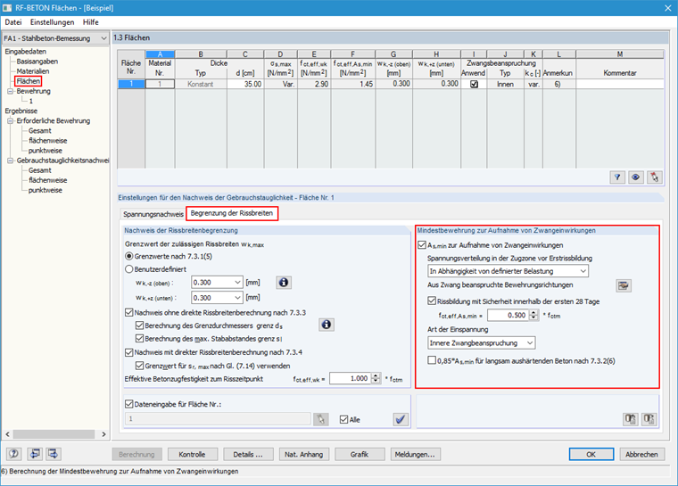
This is possible with the RF‑CONCRETE Surfaces add-on module. To do this, select a loading for the Serviceability Limit State in Window 1.1 General Data of the RF‑CONCRETE Surfaces add-on module. Then, you can define the specifications for determining the Minimum Reinforcement for Effects Due to Restraints in the Limit of Crack Width tab of Window 1.3 Surfaces.
Question
How can I determine the minimum reinforcement due to restraint for a slab in RFEM?
Use the "Independent mesh preferred" option in the FE mesh settings to create an independent FE mesh for the integrated objects. This allows you to generate a significantly more detailed and precise FE mesh for individual objects that are integrated into one another.
In the "Edit Section" dialog box, you can display the buckling shapes of the Finite Strip Method (FSM) as a 3D graphic.
In RFEM 6 and RSTAB 9, you have the option to enter "Visual Objects" as guide objects. You can import the file formats 3ds, stl, and obj.
These objects allow you to create a better reference to the dimensions.
Do you have individual column sections and angled wall geometries, and need punching shear design for them?
No problem. In RFEM 6, you can perform punching shear design not only for rectangular and circular sections, but for any cross-section shape.