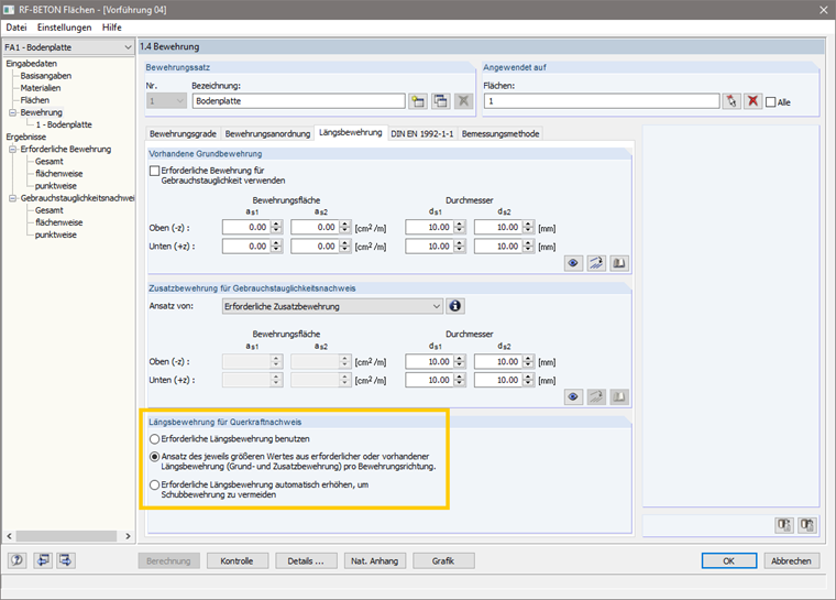
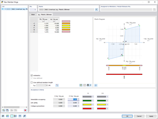
Please check the settings in the "Longitudinal Reinforcement" tab in Window 1.4. If the "Apply the greatest value from the required and provided longitudinal reinforcement (basic and additional reinforcement) per reinforcement direction" option for the shear force design is set and a provided basic reinforcement is defined additionally, the results may include a locally increased required reinforcement. The reason for this can be explained as follows: If the shear reinforcement can be avoided by using the basic reinforcement, the basic reinforcement is set as "required" because the results of the shear force design only result under the condition that the basic reinforcement is actually designed.
Question
I have problems with the graphical display of a required reinforcement in the RF‑CONCRETE Surfaces add-on module. The reinforcement is unrealistic and displayed with higher values in certain areas. The distribution does not match the moment distribution. What can I do in this case?
Do you have individual column sections and angled wall geometries, and need punching shear design for them?
No problem. In RFEM 6, you can perform punching shear design not only for rectangular and circular sections, but for any cross-section shape.
For a response spectrum analysis of building models, you can display the sensitivity coefficients for the horizontal directions by story.
These key figures allow you to interpret the sensitivity to stability effects.
The modal relevance factor (MRF) can help you to assess to which extent specific elements participate in a specific mode shape. The calculation is based on the relative elastic deformation energy of each individual member.
The MRF can be used to distinguish between local and global mode shapes. If multiple individual members show significant MRF (for example, > 20%), the instability of the entire structure or a substructure is very likely. On the other hand, if the sum of all MRFs for an eigenmode is around 100%, a local stability phenomenon (for example, buckling of a single bar) can be expected.
Furthermore, the MRF can be used to determine critical loads and equivalent buckling lengths of certain members (for example, for stability design). Mode shapes for which a specific member has small MRF values (for example, < 20%) can be neglected in this context.
The MRF is displayed by mode shape in the result table under Stability Analysis → Results by Members → Effective Lengths and Critical Loads.
You can use the "Plate Cut" component to cut plates (for example, gusset plates, fin plates, and so on). There are various cutting methods available:
- Plane: The cut is performed on the closest surface to the reference plate.
- Surface: Only the intersecting parts of plates are cut.
- Bounding Box: The outermost dimension consisting of width and height is cut out of the plate as a rectangle.
- Convex Envelope: The outer hull of the cross-section is used for the plate cut. If there are fillets at the corner nodes of the cross-section, the cut is adapted to them.