Answer:
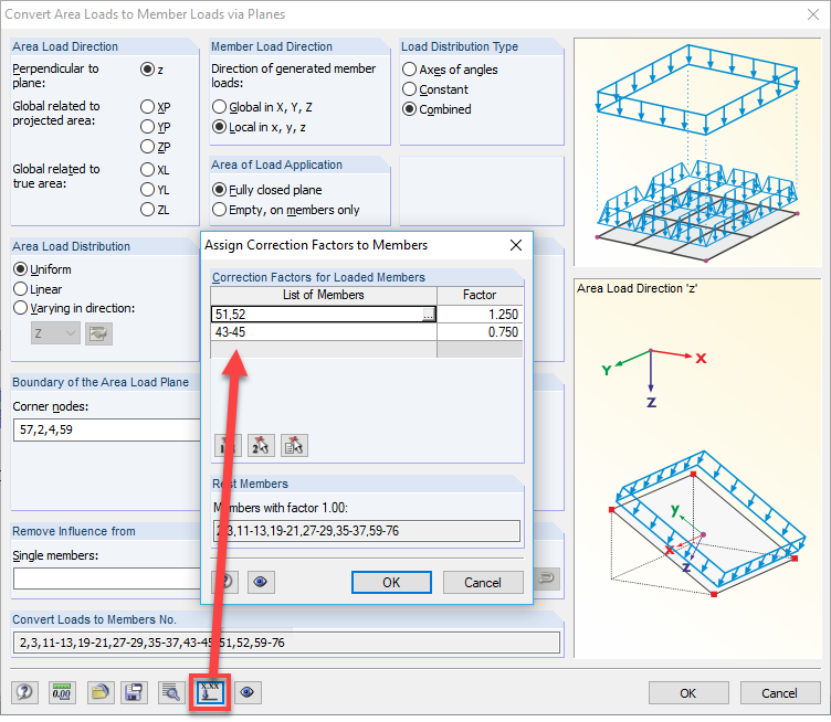
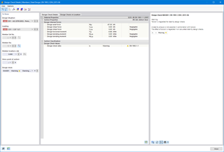
The effect of continuity can be taken into account using correction factors. It can be entered in the "Assign Correction Factors to Members" dialog box, which you can open by clicking the [Load correction factors] button.
The effect of continuity can be taken into account using correction factors. It can be entered in the "Assign Correction Factors to Members" dialog box, which you can open by clicking the [Load correction factors] button.
Ms. von Bloh provides technical support for our customers and is responsible for the development of the SHAPE‑THIN program as well as steel and aluminum structures.


Use the "Independent mesh preferred" option in the FE mesh settings to create an independent FE mesh for the integrated objects. This allows you to generate a significantly more detailed and precise FE mesh for individual objects that are integrated into one another.

In the "Edit Section" dialog box, you can display the buckling shapes of the Finite Strip Method (FSM) as a 3D graphic.

In RFEM 6 and RSTAB 9, you have the option to enter "Visual Objects" as guide objects. You can import the file formats 3ds, stl, and obj.
These objects allow you to create a better reference to the dimensions.

Do you have individual column sections and angled wall geometries, and need punching shear design for them?
No problem. In RFEM 6, you can perform punching shear design not only for rectangular and circular sections, but for any cross-section shape.

The new generation of 3D FEA software is used for the structural analysis of members, surfaces, and solids.

The Nonlinear Material Behavior add-on allows you to consider material nonlinearities in RFEM for example, isotropic plastic, orthotropic plastic, isotropic damage).

The Structure Stability add-on performs stability analysis of structures. It determines critical load factors and the corresponding stability modes.

The Torsional Warping (7 DOF) add-on allows you to consider cross-section warping as an additional degree of freedom when calculating members.

The Multilayer Surfaces add-on allows you to define multilayer surface structures. The calculation can be carried out with or without the shear coupling.

The two-part Optimization & Costs / CO2 Emission Estimation add-on finds suitable parameters for parameterized models and blocks via the artificial intelligence (AI) technique of particle swarm optimization (PSO) for compliance with common optimization criteria. Furthermore, this add-on estimates the model costs or CO2 emissions by specifying unit costs or emissions per material definition for the structural model.

The Stress-Strain Analysis add-on performs general stress analysis by calculating the existing stresses and comparing them with the limit stresses.

The Concrete Design add-on allows for various design checks according to international standards. You can design members, surfaces, and columns, as well as perform punching and deformation analyses.

The Steel Design add-on performs the ultimate and serviceability limit state design checks of steel members according to various standards.

The Timber Design add-on performs the ultimate, serviceability, and fire resistance limit state design checks of timber members according to various standards.

The Masonry Design add-on for RFEM allows you to design masonry using the finite element method. It was developed as part of the research project titled DDMaS – Digitizing the Design of Masonry Structures. The material model represents the nonlinear behavior of the brick-mortar combination in the form of macro-modeling.

The Aluminum Design add-on performs the ultimate and serviceability limit state design checks of aluminum members according to various standards.
.png?mw=600&hash=49b6a289915d28aa461360f7308b092631b1446e)
The Steel Joints add-on for RFEM allows you to analyze steel connections using an FE model. The FE model is generated automatically in the background and can be controlled via the simple and familiar input of components.

The modern 3D structural analysis and design program is suitable for the structural and dynamic analysis of beam structures as well as the design of concrete, steel, timber, and other materials.
The Structure Stability add-on performs the stability analysis of structures. It determines critical load factors and the corresponding stability modes.
The Torsional Warping (7 DOF) add-on allows for considering cross-section warping as an additional degree of freedom when calculating members.
The two-part Optimization & Costs / CO2 Emission Estimation add-on finds suitable parameters for parameterized models and blocks via the artificial intelligence (AI) technique of particle swarm optimization (PSO) for compliance with common optimization criteria. Furthermore, this add-on estimates the model costs or CO2 emissions by specifying unit costs or emissions per material definition for the structural model.
The Stress-Strain Analysis add-on performs a general stress analysis by calculating the existing stresses and comparing them to the limit stresses.
Concrete Design add-on allows for various design checks of members and columns according to international standards.
The Steel Design add-on performs the ultimate and serviceability limit state design checks of steel members according to various standards.
The Timber Design add-on performs the ultimate, serviceability, and fire resistance limit state design checks of timber members according to various standards.
The Aluminum Design add-on performs the ultimate and serviceability limit state design checks of aluminum members according to various standards.