Answer:
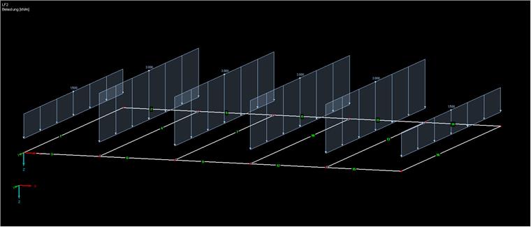
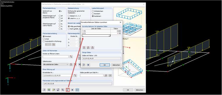
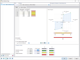
In the following example, the loads are distributed linearly, depending on the spacing of the members, without considering the respective continuous beam effect. To consider this, the correction factors are used. To assign the load correction factors to the members, select the members on which the load is to be corrected.For the edge members, the load correction factor is 0.8 since the program automatically divides the loading of the members on the edge in half (for the same span length).
The force values according to the tables for a continuous beam with five sections:
A = 0.395
B = 1.132
A = 0.395
B = 1.132
0.395/0.5 = 0.8 → When calculating with the factor 0.4, the load would be incorrect.
The members in Section 1 will be corrected to 1.1.
After clicking the [OK] button, the load is adjusted automatically.


.png?mw=600&hash=49b6a289915d28aa461360f7308b092631b1446e)


