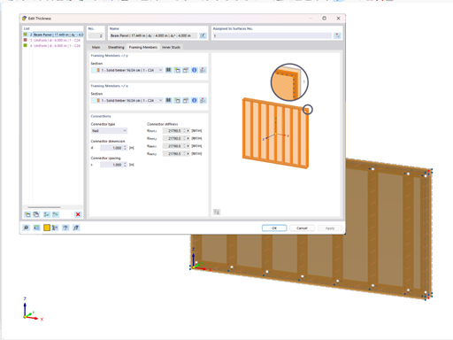
For this, a new structure is modeled. In the new modeling, the glulam beam is rigidly connected to the plate. The structure applies Load Case 1 with the load of 1.13 kN/m, Load Case 2 of 0.85 kN/m, and Load Case 3 of 0.21 kN/m. The quasi‑permanent load case combination with LK1 = 1.6 LF1 + 0.5 LF2 + LF3 governs.
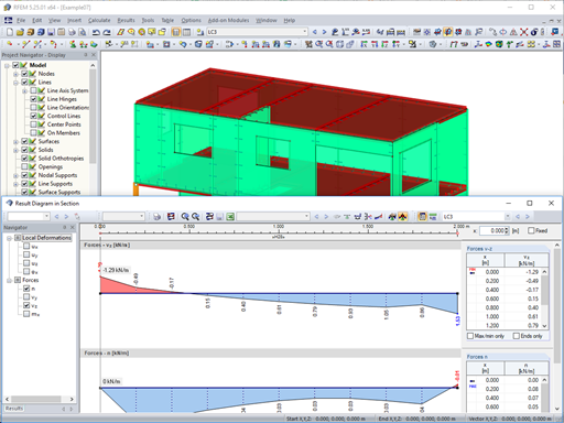
In order to consider internal forces, including the pre‑curving forces mentioned previously, a result member is defined that integrates the forces of Position 1 (described in Parts 1 and 2 of this article) and the forces of CO1. The figure shows the integration performed for both of the binding girders of the top and bottom models.
All these forces result in a deformation of 7.4 cm. However, this is subtracted from the precamber of 12 cm, so the precamber of 4.6 cm remains. Thus, the precamber is sufficient and can never fail.
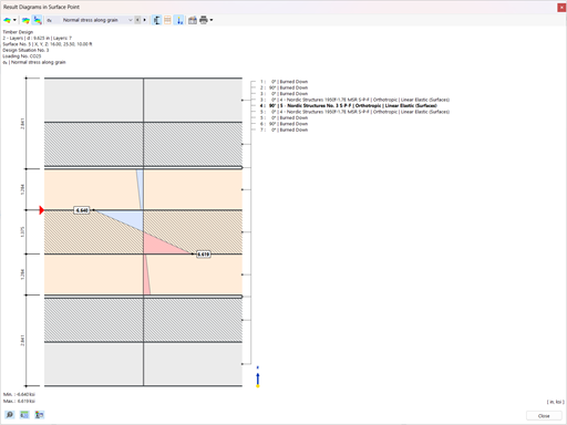
The result member design with integrated forces in RF‑TIMBER Pro shows a load of less than 60%. Therefore, all the design requirements are met.


.png?mw=512&hash=4e74affa9ad0c7b703151c5085ac9b8e59171c23)