Thus, membranes are considered separately and meshed automatically with triangles in comparison with all other elements. This global setting is covered in FE Mesh Settings.
Membrane Meshing
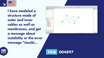
Der Formfindungsprozess mit RF-FORMFINDUNG verschiebt die Eckknoten der FE-Elemente von einer Membranfläche im Raum bis die definierte Oberflächenspannung im Gleichgewicht mit den Randreaktionen steht. Diese Verschiebung erfolgt unabhängig von der Elementgeometrie. Da diese freie Verschiebung bei Elementen mit vier Eckpunkten eine räumliche Drillung der Elementebene hervorrufen kann und dann die Gültigkeitsgrenzen der Berechnung nicht mehr eingehalten sind, sind für Formfindungssysteme generell Dreieckselemente zu empfehlen. Dreieckselemente bleiben unabhängig von der Verschiebung der Eckknoten eben und in den Anwendungsgrenzen der Berechnung.
Author
Mr. Niemeier is responsible for the development of RFEM, RSTAB, RWIND Simulation, and in the area of membrane structures. He is also responsible for quality assurance and customer support.
Links
Do you have any questions?


Length: 00:00:22 min
Length: 00:00:00 min
Length: 00:07:14 min
Length: 00:04:01 min
Length: 01:03:54 min
Length: 00:12:08 min
Length: 00:01:15 min
Length: 00:01:20 min
Length: 00:00:35 min


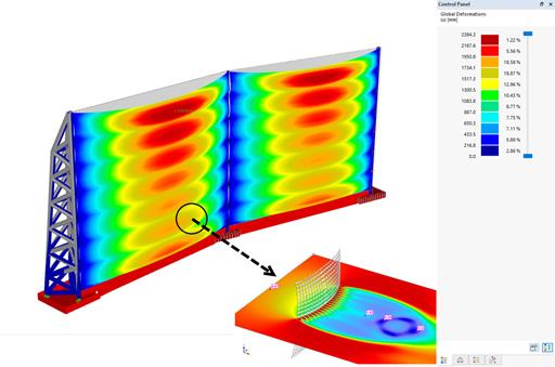
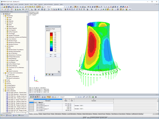
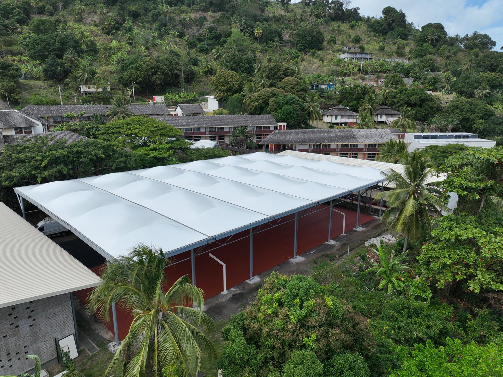
Windbreak structures are special types of fabric structures which protect the environment from harmful chemical particles, abate wind erosion, and help to maintain valuable sources. RFEM and RWIND are used for wind-structure analysis as one-way fluid-structure interaction (FSI).
This article demonstrates how to structural design windbreak structures using RFEM and RWIND.
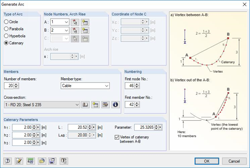
RFEM and RSTAB are able to cover a large number of branches in the building and construction industry with their generally usable structural frame analysis and FEM programs. Designing cable structures is thus also possible in both software solutions. Some assistance tools for modeling and design will be presented in the following text.

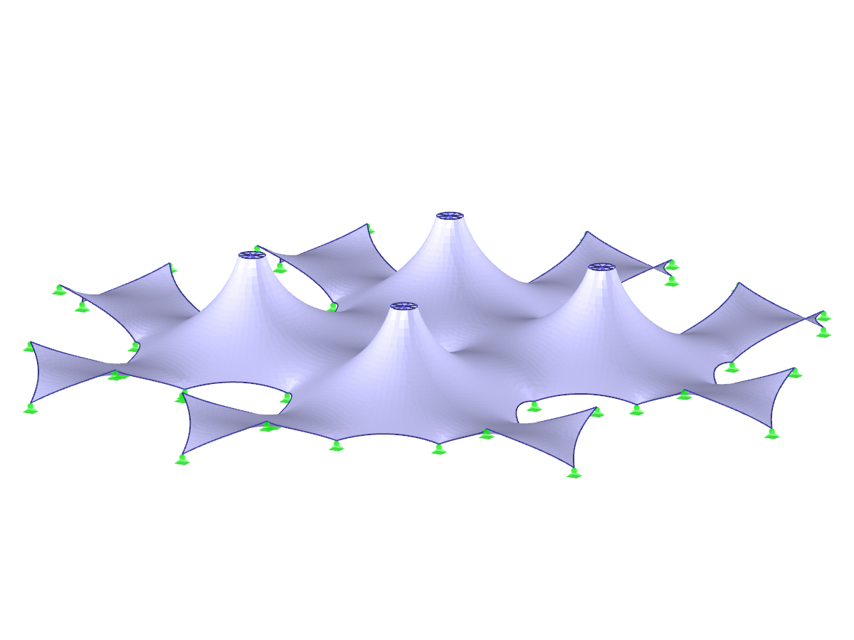
Cable and tensile membrane structures are regarded as very slender and aesthetic building structures. The partly very complex double-curved shapes can be found using suitable form-finding algorithms. One possible solution is to search for the form via the equilibrium between the surface stress (provided prestress and an additional load such as self-weight, pressure, and so on) and the given boundary conditions.
![Basic Shapes of Membrane Structures [1]](/en/webimage/009595/2419502/01-en-png-png.png?mw=512&hash=6ca63b32e8ca5da057de21c4f204d41103e6fe20)


_3.jpg?mw=350&hash=6831ba094e54512b3726fc611ff1b3a3f24436b7)

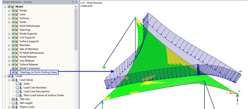
With the activated option 'Topology on Form-Finding Form' in Project Navigator - Display, the model display is optimized based on the form-finding geometry. For example, the loads are displayed in relation to the deformed system.
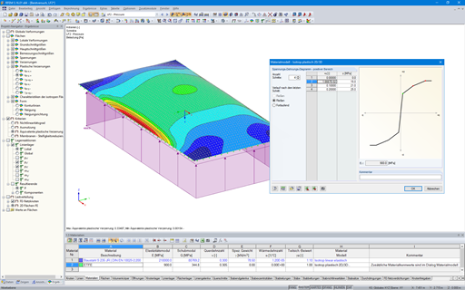
In RFEM, there is an option to couple surfaces with the stiffness types "Membrane" and "Membrane Orthotropic" with the material models "Isotropic Nonlinear Elastic 2D/3D" and "Isotropic Plastic 2D/3D" (add-on module RF-MAT NL is required).
This functionality enables simulation of the nonlinear strain behavior of ETFE foils, for example.
.png?mw=512&hash=029740dfa799337fbd84aed6cbf18113b717f8fb)
- Form-finding of:
- tension-loaded membrane and cable structures
- compression-loaded shell and beam structures
- mixed tension- and compression-loaded structures
- Consideration of gas chambers between surfaces
- Interaction with supporting structure (substructure design according to various standards)
- Surfaces as a 2D and members as a 1D element
- Definition of different prestress conditions for surfaces (membranes and shells)
- Definition of forces or geometrical requirements for members (cables and beams)
- Consideration of individual loads (self‑weight, inner pressure, and so on) in the form‑finding process
- Temporary support definitions for the form-finding process
- Automatic preliminary form-finding of membrane surfaces (more information...)
- Definition of isotropic or orthotropic material for structural analysis
- Optional definition of free polygon loads
- Transformation of form‑found shape elements into NURBS surface elements
- Possibility of combined form-finding by integration of preliminary form-finding
- Graphical evaluation of the new form using colored coordinates and inclination plots
- Complete documentation of the calculation including user-defined adaptive evaluation figures
- Optional export of the FE mesh as a DXF or Excel file
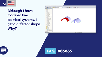
Although I modeled two identical systems, I got a different shape. Why?
It seems that the members stay not deformed after my RF‑FORM‑FINDING calculation. What did I wrong?
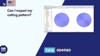
Can I export my cutting pattern?
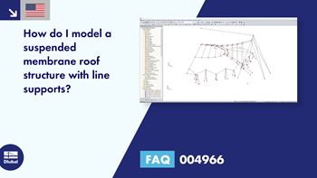
How do I model a suspended membrane roof structure with line supports?
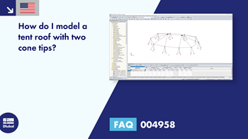
How do I model a tent roof with two cone tips?
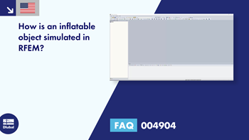
How is an inflatable object simulated in RFEM?


.png?mw=350&hash=e3f5898d72f463e9b3e774659aabcb220466c522)

Recommended Products for You
RFEM 6 | Main Program RFEM 6

The new generation of 3D FEA software is used for the structural analysis of members, surfaces, and solids.
Price of First License
4,170.00 USD
RFEM 6 | Additional Analysis

The Form-Finding add-on finds the optimal shape of members subjected to axial forces and tension-loaded surface models. The shape is determined by the equilibrium between the member axial force or the membrane stress and the existing boundary conditions.
Price of First License
2,060.00 USD
RFEM 5 | Main Program RFEM

Structural engineering software for a finite element analysis (FEA) of planar and spatial structural systems consisting of plates, walls, shells, members (beams), solids, and contact elements
Price of First License
4,080.00 USD
RFEM 5 | Tensile Membrane Structures

Form-finding of tensile membrane and cable structures
Price of First License
2,060.00 USD
RFEM 5 | Tensile Membrane Structures

Generation of cutting patterns for tensile membrane structures
Price of First License
2,510.00 USD
RFEM 6 | Design

The Steel Design add-on performs the ultimate and serviceability limit state design checks of steel members according to various standards.
Price of First License
2,550.00 USD