Application Area
The application of the design rules for silos and tanks is subjected to geometrical limitations. In [1], the geometric dimensions are limited to hb / dc < 10 with hb < 100 m and dc < 60 m. In addition, the application limits depend on the cross-section shape of the silo and on the stored solids.
Properties of Particulate Solids
Annex E of [1] specifies the parameters of the most common solids stored in silos, showing the range of particulate solid properties. Furthermore, Section 4 and Annex C of [1] describe the test methods for determining the properties of the stored solids.
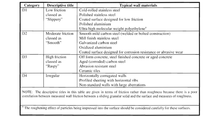
Wall frictional properties of the particulate solids take into account the roughness of wall surfaces where the solids slide along. Table 4.1 of [1] describes the various categories of wall surfaces. The categories of the wall surfaces are shown in the table below. Annex D.2 of [1] also provides information for the evaluation of the wall friction coefficient for the D4 category.
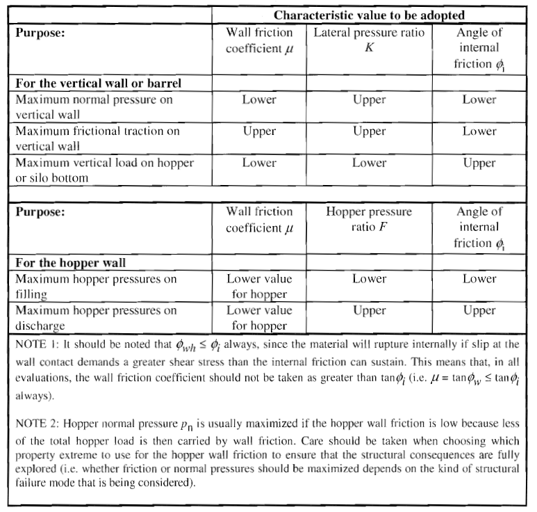
You should always determine the loads of a load case for a particular combination of the relevant solid properties. For each of these load cases, the extreme values are reached when the solid properties take different extreme values within the discharge flow of the particulate solids. The extreme values of the bulk material parameters to be used for each of the load cases to be analyzed are given in Table 3.1 of [1]. The relevant parameters for various load applications are included in the following table.
Structural Class
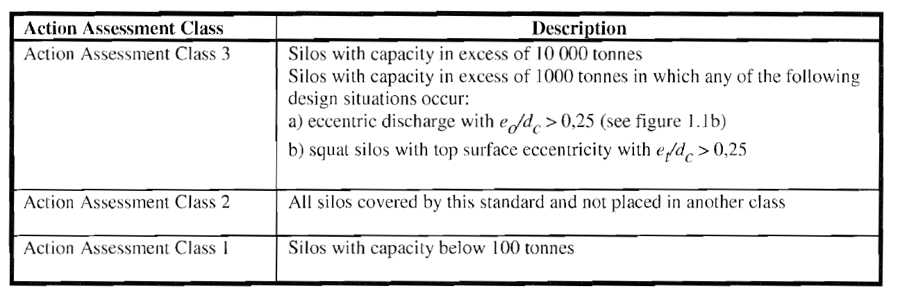
Silo cells are divided into three action assessment classes according to their storage capacity and eccentricity in compliance with Table 2.1 of [1].
Various differentiated or simplified loading assessments are adopted according to the respective action assessment class.
Loads on Vertical Walls of Silos
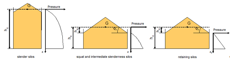
Loads on the vertical walls of silos are subjected to a differentiated calculation considering the silo slenderness. A distinction is made between:
- slender silos (hc / dc ≥ 2.0),
- silos with medium slenderness (1.0 < hc / dc < 2.0),
- low silos (0.4 < hc / dc ≤ 1.0), and
- retaining wall silos (hc / dc ≤ 0.4 and horizontal silo floor)
Symmetrical Loads
Symmetrical loads are fixed loads that are uniformly distributed over the silo circumference. Discharge loads arise when the uniform loads in full condition are increased by a load-magnifying factor.
Asymmetrical Loads
Besides the fixed loads, additional free loads are usually to be applied. Distributions of unsymmetrical loads (patch loads) in a silo are caused by actions due to imperfections or eccentricities during filling and discharge of solids.
For thick-walled circular silos, the patch load shall be applied to a square area with the side length s on opposite sides. In the case of non-circular silos, the patch loads can be taken into account by increasing the symmetrical loads. The outward patch pressure should be taken to act on a horizontal band on the silo wall at any level, over a vertical height s.
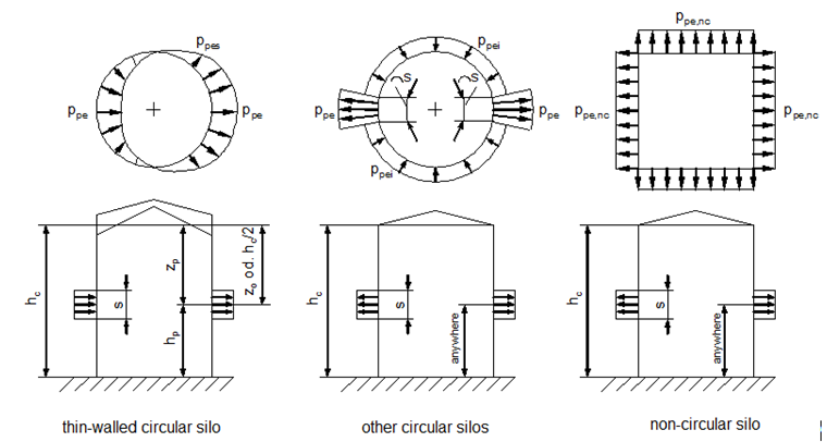
Generally, it is unnecessary to apply the patch loads in the case of squat and intermediate slenderness silos.
For silos in Action Assessment Class 2, the patch load method may be approximately used by uniformly increasing horizontal pressures.
Discharge Loads with Large Eccentricities
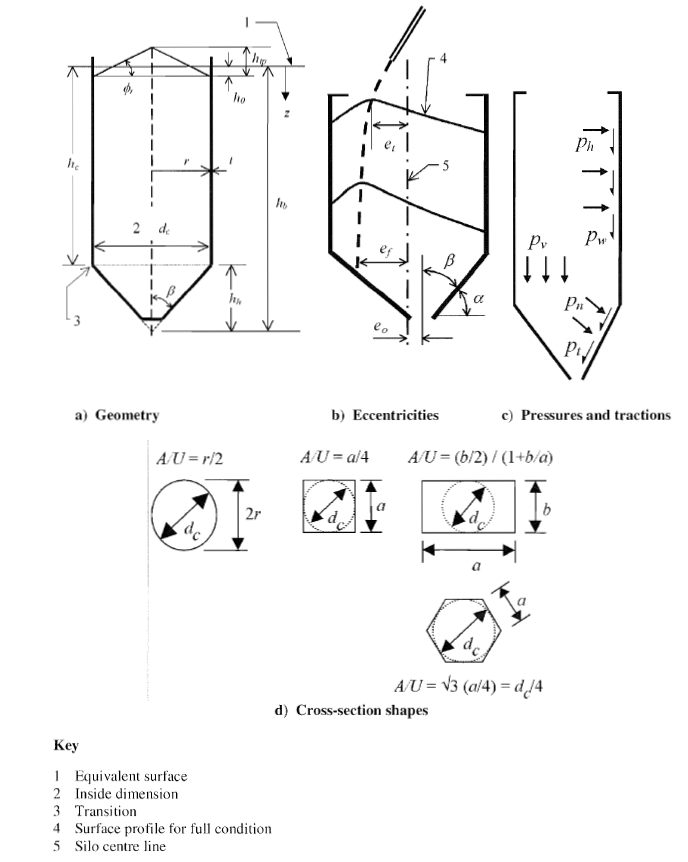
According to [1], loads due to large discharge eccentricities should be used as a separate load case. The development of this loading assessment is based on the premise that a flow channel may occur near the wall as a result of large eccentric discharge. A circular flow channel is assumed, which is constant due to the height of the silo wall, and intersects the silo wall at an opening angle θc.
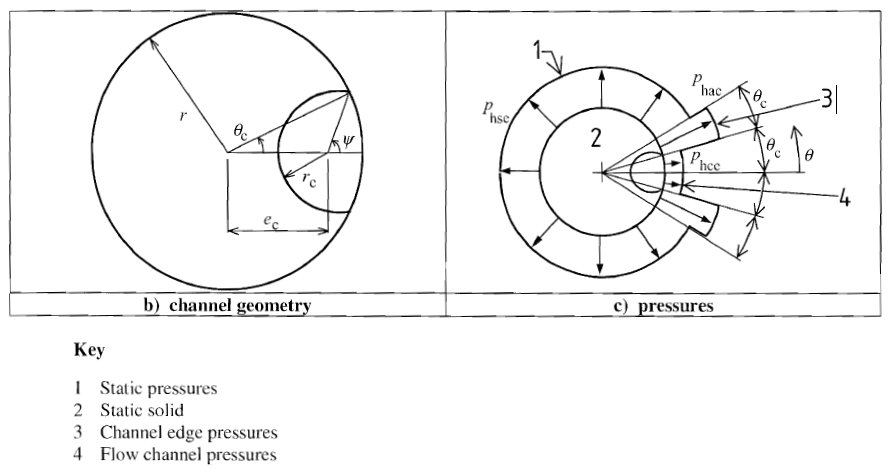
However, a theoretical prediction of the geometric shape of a discharge hopper is hardly possible with the tools currently available. Therefore, the flow channel must be specified. The calculation is performed with at least three different flow channel radii rc in order to determine the apparent variations of the flow channel.
Lower horizontal pressures occur outside the flow channel in the contact areas of the flowing solid and the silo wall. The loads of the filling load case apply in the latter area. The pressure is increased directly next to the flow channel up to the opening angle of 2 θc.
Large Eccentricity Filling Loads
Loads due to eccentric filling must be considered for squat or intermediate slenderness silos.
EN 1991‑4 [1] explains the determination of the additional vertical force (compressive) in the wall per unit length of circumference at any depth zs below the point of highest wall contact. This force per unit circumference should be added to the force arising from wall friction.
Loads on Silo Hoppers and Silo Bottoms
The loads on the walls of silo hoppers should be determined with regard to the steepness of the hopper walls according to [1].
The standard distinguishes between flat bottoms as well as steep and shallow hoppers. In the case of steep hoppers, there is an additional distinction between the load cases of filling and discharge. Kick load at the transition from the vertical walled section to the hopper is already included in the load distributions.
Annex G of [1] provides alternative rules for pressures in hoppers.
Example
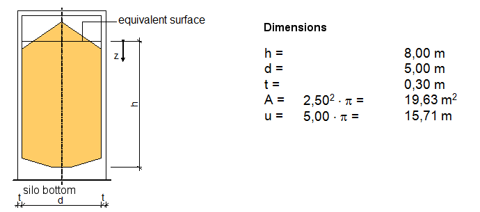
The example presents a free-standing cylindrical silo for cement with a diameter of 5.00 m and a maximum bulk unit depth of 8.00 m. The silo is made of reinforced concrete with a wall thickness of 0.30 m.
Bulk Material
The following parameters for bulk solids were taken from Table E.1 of [1].
- unit weight (upper) γu = 16.00 kN/m³
- angle of repose Φr = 36.00°
- angle of internal friction (mean) Φim = 30.00°
- conversion factor aφ = 1.22
- lateral pressure ratio (mean) Κm = 0.54
- conversion factor aΚ = 1.20
- wall friction coefficient (wall type D3) μm = 0.51 (for concrete)
- conversion factor aμ = 1.07
- characteristic value for patch load Cop = 0.50
Characteristic Properties of Bulk Solids
In order to determine the characteristic values of the lateral pressure ratio, wall friction coefficient, and angle of internal friction, the listed mean values of the particulate solids must be scaled using the conversion factors. The conversion factors ax are specified in Table E.1 of [1] for the available particulate solids.
Upper and lower characteristic values of the lateral pressure ratio
Κu = aΚ ∙ Κm = 1.20 ∙ 0.54 = 0.648
Κl = Κm / aΚ = 0.54 / 1.20 = 0.450
Upper and lower characteristic values of the wall friction coefficient
μu = aμ ∙ μm = 1.07 ∙ 0.51 = 0.546
μl = μm / aμ = 0.51 / 1.07 = 0.477
Upper and lower characteristic values of the angle of internal friction
Φiu = aΦ ∙ Φim = 1.22 ∙ 30.00° = 36.60°
Φiu = Φim / aΦ = 30.00° / 1.22 = 24.59°
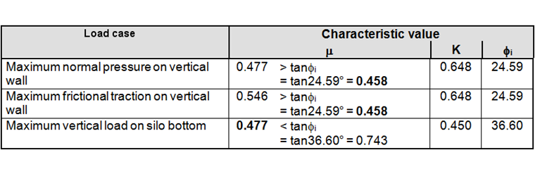
Governing characteristic values for different load applications
The evaluation of each load case should be made using a single set of consistent values of the solids properties, so that each limit state corresponds to a single defined stored solid condition. The extreme values of solids properties that should be adopted for each load case is given in the following table.

The angle of wall friction must always be less than or equal to the angle of internal friction of the stored solid; that is, Φwh ≤ Φi. Otherwise, the material will rupture internally if slip at the wall contact demands a greater shear stress than the internal friction can sustain. This means that, in all cases, the wall friction coefficient should not be taken as greater than tanΦi (μ = tanΦw ≤ tanΦi). This is considered in the table above, where the relevant values are in bold.
Actions
The actions are determined on the basis of DIN EN 1991-4 1. Only the filling loads on vertical walls and the vertical pressures on the flat bottoms of the silo should be calculated here.
Silo Classification
The classification of the silo is based on the slenderness and the action assessment class.
Slenderness
1.0 < hc / dc = 8.00 / 5.00 = 1.6 < 2.0
The silo is classified as an intermediate slenderness silo in accordance with 1.5.21 of [1].
Action Assessment Class
Capacity = V ∙ γu = 157.08 ∙ 16.00 = 2513.27 ≙ 2513.27 / 9.80665 = 256.28 t
According to Table 2.1 of [1], at least Action Assessment Class 2 must be selected.
Construction Form
dc / t = 5.00 / 0.30 = 16.7 < 200
The silo is classified as a thick‑walled silo in accordance with 1.5.43 of EN 1991‑4 [1].
Symmetrical Filling Loads on Vertical Silo Walls
Horizontal Pressure
Janssen characteristic depth zo
Vertical Distance ho
For a symmetrically filled circular silo, the vertical distance ho between the equivalent surface of the solid and the highest solid‑wall contact is calculated as follows:
Parameter n
Asymptotic Horizontal Pressure at Great Depth Due to Stored Bulk Solids pho
pho = γ ∙ K ∙ zo = 16.00 ∙ 0.648 ∙ 4.22 = 43.70 kN/m² (5.73)
Horizontal Pressure phf(z)
phf(0.61) = 0 kN/m²
phf(1.61) = 13.26 kN/m²
phf(2.61) = 20.93 kN/m²
phf(3.61) = 25.83 kN/m²
phf(4.61) = 29.19 kN/m²
phf(5.61) = 31.62 kN/m²
phf(6.61) = 33.43 kN/m²
phf(7.61) = 34.83 kN/m²
phf(8.00) = 35.29 kN/m²
Wall Frictional Traction
Janssen characteristic depth zo
Vertical distance ho
For a symmetrically filled circular silo, the vertical distance ho between the equivalent surface of the solid and the highest solid‑wall contact is calculated as follows:
Parameter n
Asymptotic horizontal pressure at a great depth from stored bulk material pho
pho = γ ∙ K ∙ zo = 16.00 ∙ 0.648 ∙ 4.22 = 43.70 kN/m² (5.73)
Wall frictional traction pwf(z)
pwf(0.61) = 0 kN/m²
pwf(1.61) = 6.07 kN/m²
pwf(2.61) = 9.58 kN/m²
pwf(3.61) = 11.82 kN/m²
pwf(4.61) = 13.36 kN/m²
pwf(5.61) = 14.47 kN/m²
pwf(6.61) = 15.30 kN/m²
pwf(7.61) = 15.94 kN/m²
pwf(8.00) = 16.15 kN/m²
Vertical Pressure
Janssen characteristic depth zo
Parameter n
Vertical pressure pvf(z)
pvf(0.61) = 9.69 kN/m²
pvf(1.61) = 23.65 kN/m²
pvf(2.61) = 34.51 kN/m²
pvf(3.61) = 43.27 kN/m²
pvf(4.61) = 50.52 kN/m²
pvf(5.61) = 56.65 kN/m²
pvf(6.61) = 61.92 kN/m²
pvf(7.61) = 66.50 kN/m²
pvf(8.00) = 68.15 kN/m²
Vertical forces (compressive) in the wall nzSk(z)
nzSk(z) = μ ∙ pho(z) ∙ (z - zv) (5.81)
nzSk(0.61) = 0.00 kN/m
nzSk(1.61) = 2.55 kN/m
nzSk(2.61) = 8.97 kN/m
nzSk(3.61) = 18.02 kN/m
nzSk(4.61) = 28.96 kN/m
nzSk(5.61) = 41.30 kN/m
nzSk(6.61) = 54.72 kN/m
nzSk(7.61) = 68.98 kN/m
nzSk(8.00) = 74.81 kN/m
Asymmetric Filling Loads on Vertical Silo Walls
Dimension of the patch load zone
Characteristic depth zo according to the Janssen theory
Vertical Distance ho
For a symmetrically filled circular silo, the vertical distance ho between the equivalent surface of the solid and the highest solid‑wall contact is calculated as follows:
Parameter n
Asymptotic Horizontal Pressure at Great Depth Due to Stored Bulk Solids pho
pho = γ ∙ K ∙ zo = 16.00 ∙ 0.648 ∙ 4.22 = 43.70 kN/m² (5.73)
Load increase factor Cpf of the partial area load for the filling load case
Patch load for the filling load case
ppf(0.61) = 0 kN/m²
ppf(1.61) = 0.83 kN/m²
ppf(2.61) = 1.30 kN/m²
ppf(3.61) = 1.61 kN/m²
ppf(4.61) = 1.82 kN/m²
ppf(5.61) = 1.97 kN/m²
ppf(6.61) = 2.08 kN/m²
ppf(7.61) = 2.17 kN/m²
ppf(8.00) = 2.20 kN/m²
ppfi(0.61) = 0 kN/m²
ppfi(1.61) = 0.12 kN/m²
ppfi(2.61) = 0.19 kN/m²
ppfi(3.61) = 0.23 kN/m²
ppfi(4.61) = 0.26 kN/m²
ppfi(5.61) = 0.28 kN/m²
ppfi(6.61) = 0.30 kN/m²
ppfi(7.61) = 0.31 kN/m²
ppfi(8.00) = 0.31 kN/m²
Loads on horizontal silo floors
Vertical pressure acting on flat bottoms of intermediate slenderness silos cannot be taken as uniform, and the calculation is based on the following load assessments:
The bottom load magnifying factor Cb applies to silos of Action Assessment Class 2 under the condition that the stored solids do not tend toward dynamic behavior during the discharge process.
The vertical pressure pvsq on the bottom of a silo may be taken to act both after filling and during discharge.
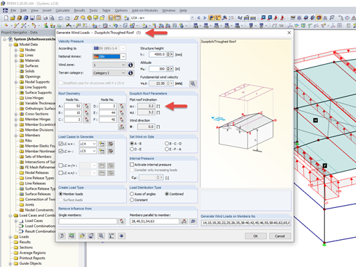
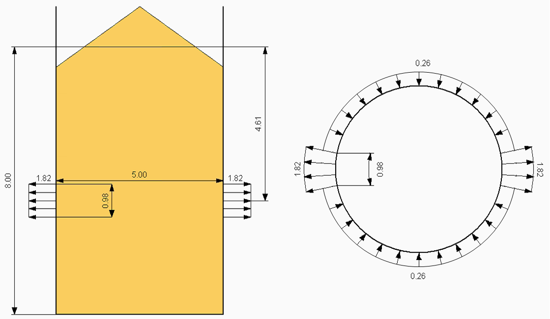
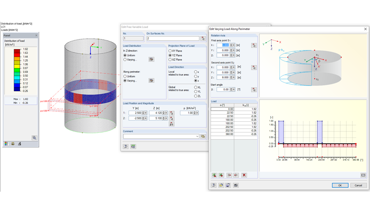
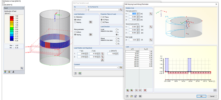
Entering Loads in RFEM
The defined load can be entered in RFEM. Figure 13 shows the exemplary filling patch load for z = 4.61 m. This load can be entered in RFEM as a free variable load. The load input is displayed in Figure 14.
Literature
[1] Eurocode 1: Actions on Structures - Part 4: Silos and Tanks; EN 1991‑4:2010‑12