According to 6.4.2 (2) [1], control perimeters at a distance of less than 2d should be considered where the concentrated force is opposed by high pressure (for example, soil pressure on a base). The basic control perimeter area is usually determined iteratively.
The German National Annex [2], NCI to 6.4.4 (2), allows for a simplified calculation in the case of floor slabs and slender foundations with λ = aλ / d > 2, where aλ is the shortest distance between the loaded area and the foundation edge). In this case, the basic control perimeter can be applied at a distance of 1d.
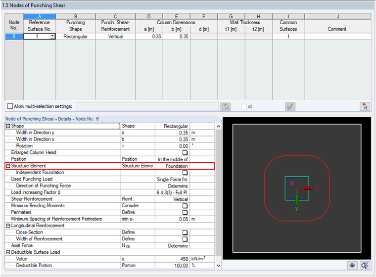
Generally, RF-PUNCH Pro determines the basic control perimeter area in foundations and floor slabs iteratively. In order to perform the punching shear design on a foundation or a floor slab, it is necessary to select "Foundation" as "Structure Element" in Window 1.5 Nodes of Punching Shear in RF‑PUNCH Pro.
The resulting effective force is calculated according to Expression (6.48) of [1]: VEd,red = VEd - ΔVEd. According to 6.4.4 (2), ΔVEd is the net upward force within the control perimeter considered (upward pressure from the soil minus the self‑weight of the base).
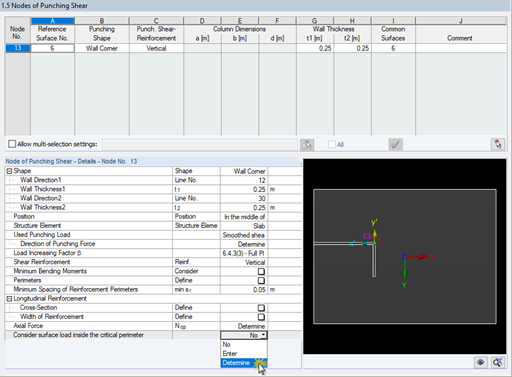
The ground pressure, which should be set as a favorable action, can also be entered in Window 1.5 Nodes of Punching Shear at the end of the table, including details of the individual node of punching shear. The values of the deductible surface load and the percentage deductible portion should be specified here. Furthermore, it is necessary to define the maximum deductible surface load within the iteratively determined basic control perimeter. For this, "acrit" is set.

Example of Iterative Determination of Basic Control Perimeter Area
The iterative determination of the basic control perimeter will now be checked in RF‑PUNCH Pro using a comparative calculation, in which the individual control perimeters are set manually.
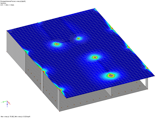
First, a small foundation plate (plate thickness dPL = 500 mm, length ⋅ width = 2.00 m ⋅ 2.00 m) is modeled in RFEM, and a short reinforced concrete column (cross‑section: rectangle 350 ⋅ 350 mm, length L = 2.00 m) is applied on it. As a material, the concrete of strength class C30/37 is set. The self-weight of the structure will be considered, too. A column is loaded by vertical loads at the column head. The self‑weight load case includes the vertical load of Gk = 800 kN; the imposed load case includes the vertical load of Qk = 450 kN. Thus, the load design value of VEd = 1763.27 kN results for the load combination CO1 = 1.35 ⋅ G + 1.50 ⋅ Q.
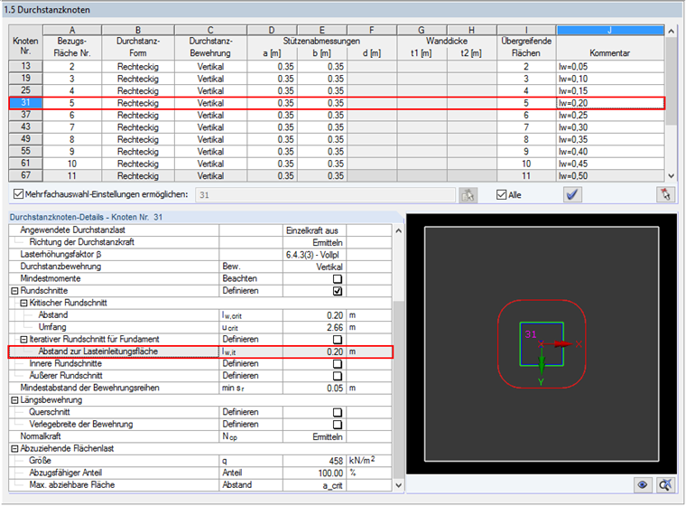
In order to determine the deductible surface load, the contact stresses σz for CO1 are calculated in RFEM. In our example, the contact stress of 458 kN/m² applies and is entered as the deductible surface load value in Window 1.5, as you can see in Image 02.
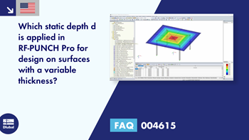
The location of longitudinal reinforcement in the foundation plate can be defined in Window 1.4. In this example, the concrete cover of d1 = 5.50 cm and d2 = 6.50 cm is set. The resulting statical height d is 44.0 cm. Basic reinforcement for determining the punching resistance of the foundation plate is not specified in this example.
After performing the calculation using the data mentioned above, the design criterion of 0.87 can be found in Result Window 2.1. Result details show the intermediate values used to determine the resulting applied shear force VEd,red.
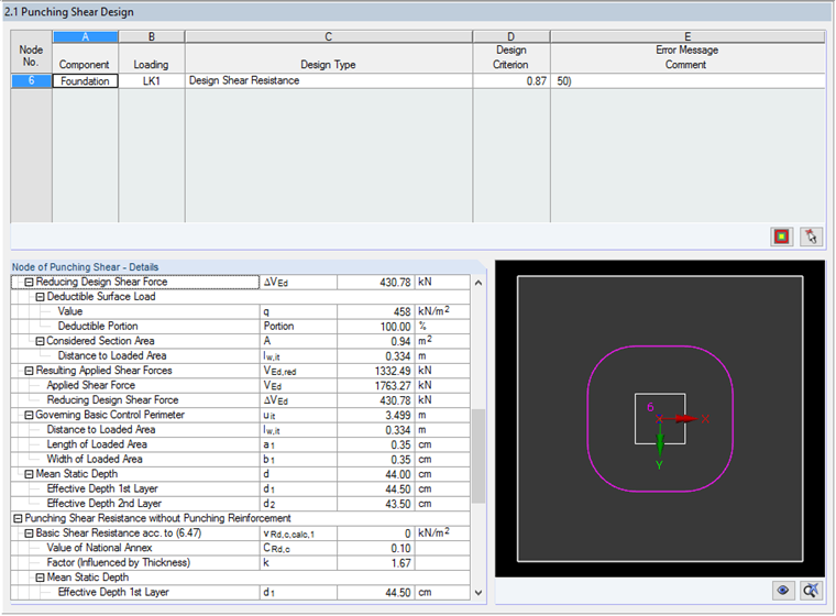
In this case, RF-PUNCH Pro determines the basic control perimeter area at a distance of lw,it = 0.334 m from the edge of the loaded area. The resulting area within the basic control perimeter is:
A = 0.334² ∙ π + 4 ∙ 0.334 ∙ 0.35 + 0.35² = 0.94 m²
Based on this, the resulting reducing shear force ΔVEd or resulting applied shear force VEd,red is:
ΔVEd = 0.94 m² ∙ 458 kN/m² = 430.78 kN
VEd,red = 1763.27 kN - 430.78 kN = 1332.49 kN

Check of Iteratively Determined Basic Control Perimeter Area
The results of the first calculation and the basic control perimeter area iteratively determined in RF-PUNCH Pro will be now checked in the second calculation.
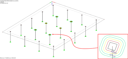
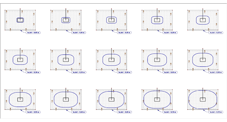
For this, the basic control perimeter area can be specified manually before starting the calculation in RF-PUNCH Pro. The distance will be incrementally increased, starting with the basic control perimeter area of ΔL = 0.05 m. Punching on a total of 15 manually defined control perimeters at a distance from lw,def = 0.05 m to 0.75 m will be examined.
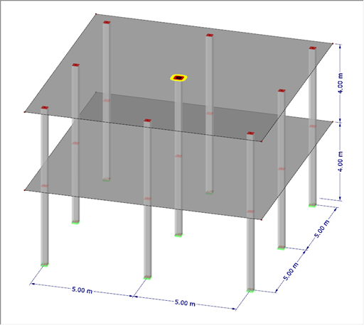
As you can see in Image 05, it is reasonable to copy the defined foundation (including loads) several times for this calculation. Thus, it is possible to examine 15 different calculation methods in one calculation process. In Window 1.5, you can set the distance to the loaded area individually for each node of punching shear.
After calculating all 15 variants with the user-defined area of the basic control perimeter, the results can be evaluated. The following image shows that the result of the first calculation (with the iterative determination of the basic control perimeter area) can be confirmed. The maximum design criterion is between lw,def = 0.30 and 0.35 m (the previous iteratively determined distance lw,it = 0.334 m).
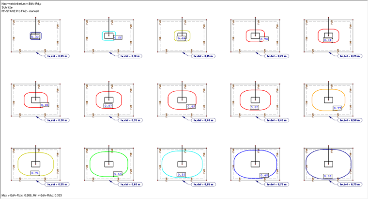
Subsequently, the results of the calculation with manual definition of the basic control perimeter area can be evaluated graphically in the form of an Excel chart. For this, the quotient of the resulting applied shear force and punching shear resistance (νEd,red / νRd,c) is applied to the vertical axis. The horizontal axis is used for the quotient of the distance to the loaded area and the static height (ait / d).
Reference values from the first calculation:

The results of the first calculation using iterative determination of the basic control perimeter can thus be confirmed.