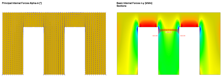
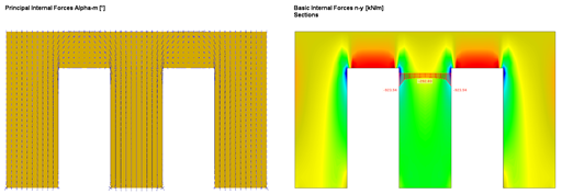
In order to compare the results with the equivalent member method or to create an identical precondition, only the results of the wall section between the doors are considered. Since the load introduced to the respective wall section by the door lintels is concentrated on the corner area of the door openings, there is also (locally) a larger axial force than in the middle of the wall section (see Figure 1).
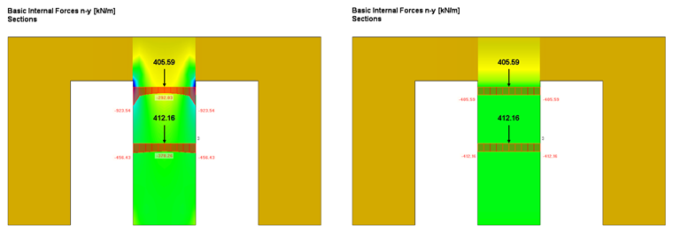
The Equivalent Member Method did not consider these local effects, as they were calculated with a "blurred" axial force. In order to consider this also in the surface design (to get the same conditions), an average region is entered that "distributes" the internal forces on the respective wall section (see Figure 2). The local stresses are considered in the design, of course, and will not be further explained in this article.
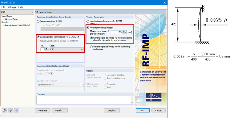
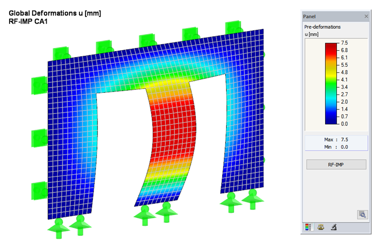
In order to consider pre-deformation without stress (imperfection) according to [1] Section 5.4.4(2), the RF-IMP add-on module generates a pre-deformed FE mesh from the buckling mode, which was determined in RF-STABILITY (see Figures 3 and 4). The value of 7.5 mm results from Equation 5.2 of [1].
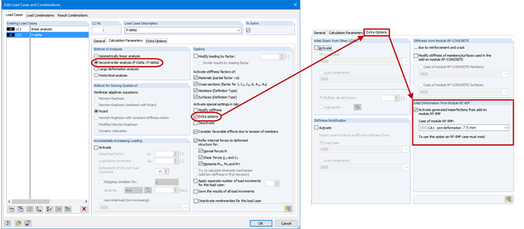
To determine the internal forces according to the second-order analysis, it is necessary to activate the pre-deformed FE mesh in the Extra options of the respective load case or load combination (see Figure 5).
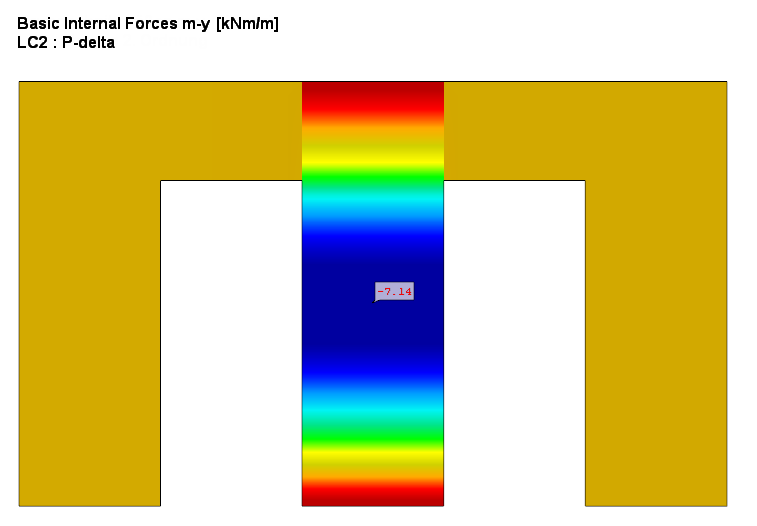
Thus, additional bending moments arise for the results in addition to the axial forces (see Figure 6), which must be considered in the design.
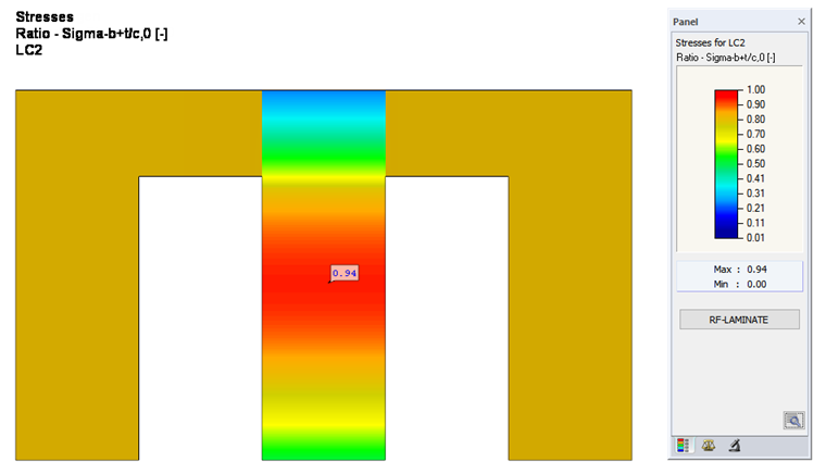
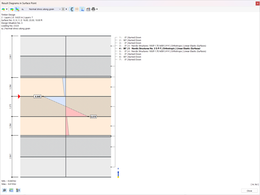
The subsequent calculation in RF-LAMINATE provides the design ratio of 94% for the wall section susceptible to buckling (see Figure 7). The design ratio with the equivalent member method amounts to 144%. Due to the very low critical load factor, this difference should not be interpreted as linear at all.
The differences are caused to a small, negligible extent by the additional stiffness that results from the door lintels in the analysis of the surface model. However, the main difference between the calculation using the Equivalent Member Method and the calculation according to the second-order analysis is caused by a different application of stiffnesses. While the slenderness is calculated with the 5% quantile values of the stiffnesses for the equivalent member design, the design with the second-order analysis according to [1], Section 2.2.2, or [2], Section NCI NA.9.3.3 is calculated with the design values of the stiffnesses. However, in [3] Section 8.5.1(2) and [4] it is pointed out that, for the calculation of individual components, the 5% quantile value of the stiffness properties divided by the partial safety factor is to be used, rather than the design values. This affects the additional bending moment resulting from the pre-deformation when calculating according to the second-order analysis. In addition to this, the limit design stress according to the equivalent member method decreases directly with kmod, while the limit design stress according to the second-order analysis barely changes [5]. Therefore, the stiffness should always be reduced additionally by the modification factor kmod in compliance with [5], Section E 8.5.1.
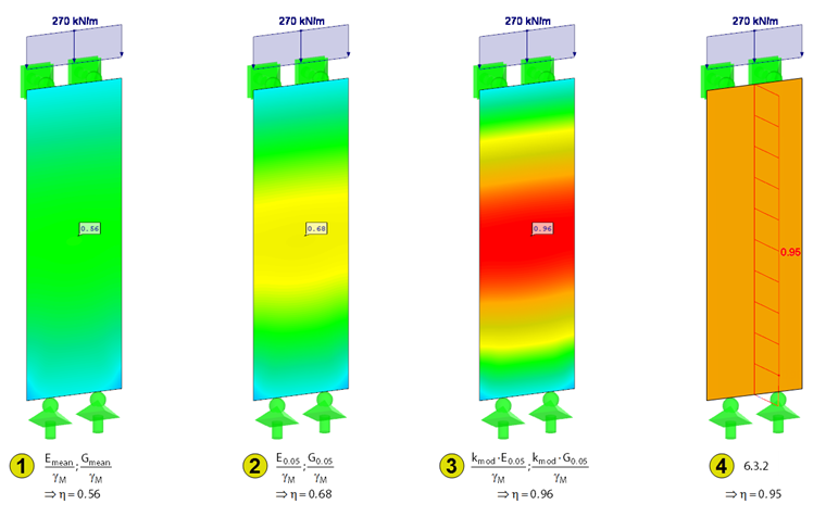
In order to analyze the various cases, Figure 8 shows on a simplified structure what this actually means. The load is reduced until the equivalent member method design is fulfilled (Case 4). For Cases 1 to 3, the stability analysis was performed with internal forces on the pre-deformed model. In Case 1, the stiffness is considered with the design values. Case 2 uses the 5% quantile of the stiffness properties and Case 3 additionally uses the stiffness properties reduced by kmod. As confirmed in [6], the result with the best conformity is provided by the equivalent member method for Case 3. It is important for a comparison that it is not the utilization that is compared, but the maximum ultimate load. While the design ratio increases linearly with an increase in the load for the equivalent member method, this occurs non-linearly for the design according to the second-order analysis. As written above, a comparison only makes sense in Case 3 and only with the maximum ultimate loads; that is, when the design ratio is 100%.
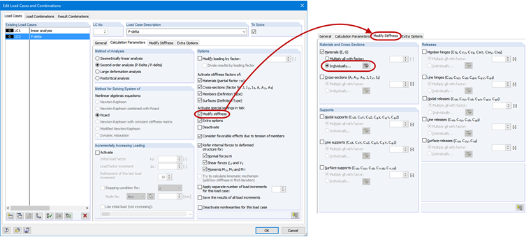
If the reductions by kmod are not considered for the stiffness, the influence of the moisture content and load duration on the stiffness properties, and thus on the determination of internal forces, is also not considered. Therefore, the design applying kmod of less than 1.0 can be incorrect. The modified stiffnesses can be considered for each load combination; for example, as shown in Figure 9.


.png?mw=512&hash=4e74affa9ad0c7b703151c5085ac9b8e59171c23)


.jpg?mw=350&hash=8f312d6c75a747d88bf9d0f5b1038595900b96c1)


.png?mw=600&hash=49b6a289915d28aa461360f7308b092631b1446e)