This article describes how RFEM and RSTAB set the member position automatically and how it can be adjusted using member rotation angles, if required.
Local Member Axes
The member-related coordinate system with the axes x, y and z is defined as right-angled with right-hand screws. The local member axis x always represents the centroidal axis of the member. It connects the initial node to the end node while the positive direction of the axis x is oriented from the initial node i to the end node j of the member. In the case of symmetrical cross-sections, the local axes y and z represent the principal axes of the member (these axes are indicated as u and v in the case of asymmetrical cross-sections). The axis y is the “major” axis of the cross‑section.
Member Rotation Angle β
If a member has a rotation about its longitudinal axis, this rotation can be defined by the angle β. The position and thus the local member coordinate system xyz is clearly described by specifying the initial node i and the end node j as well as the rotation angle β.
The program then defines the position of the local axes y and z automatically: The axis z is located in space in the way that the Z‑part of the directional arrow related to the global coordinate system always points to the positive global direction Z. The axis y is then obtained according to the right-hand rule. From this position, the member can be rotated using the rotation angle β, which indicates the rotation of the local system x, y, z against the reference system x', y', z'. In the case of the default setting β = 0°, the reference system is the local system at the same time. In the case of the positive angle β, the directions y and z rotate about the longitudinal member axis (local axis x) as in the case of a right-hand screw.
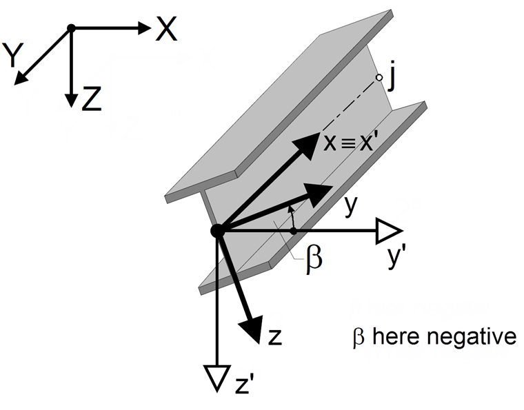
If the local system xyz is right-screwed rotated by 90°, the axis y is in the position of the axis z before the rotation.
Figure 02 shows the left-screwed rotation. The angle β should be entered as negative in this case.
Member Orientation in Case of a Non-Horizontal Member Position
If the member is in the horizontal position, the orientation and rotation are clear, as shown in Figure 02. However, if the member is located in space, the program orients the member according to the following rules.
For a member rotation angle β = 0°, two cases are possible.
1. Case: General position of the member, β = 0°
The reference axis y' is parallel to the global XY plane. The reference axis z' is perpendicular to the axes x' and y' while its Z‑component always points in the direction of the global axis Z. If the Z-axis is defined downwards in General Data, it points in the direction of the positive Z-component; if the Z-axis is defined upwards, it points in the direction of the negative Z-component. The directions of the axes follow the right-hand rule.
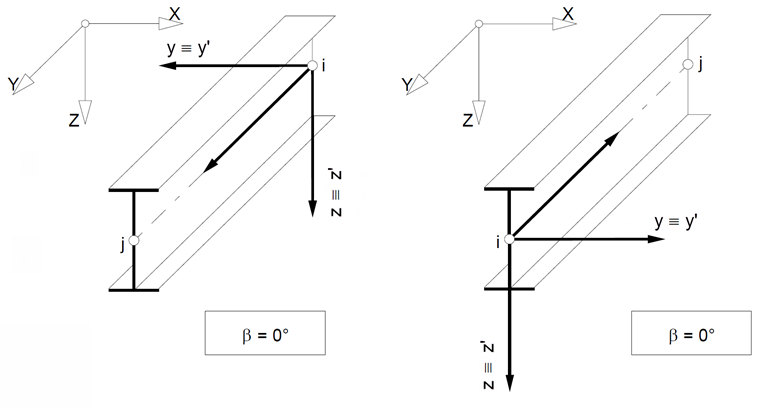
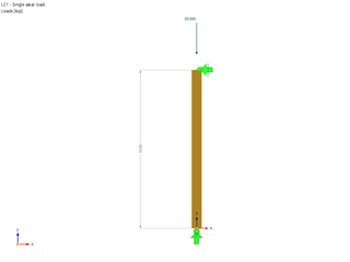
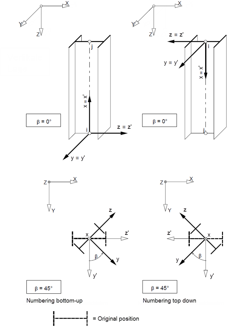
2. Case: Vertical position of the member, β = 0°
The reference axis y' points in the direction of the global Y‑axis. The axis z is obtained by using the right-hand rule; if β = 0°, it points in the direction of the global X-axis.
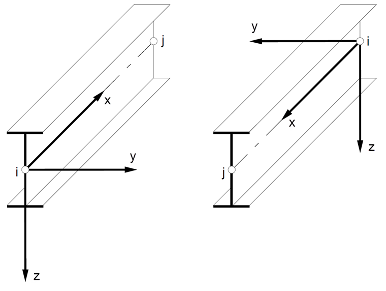
For a member rotation angle of ±90° and 180°, the program applies the following assumptions for members in the vertical position:
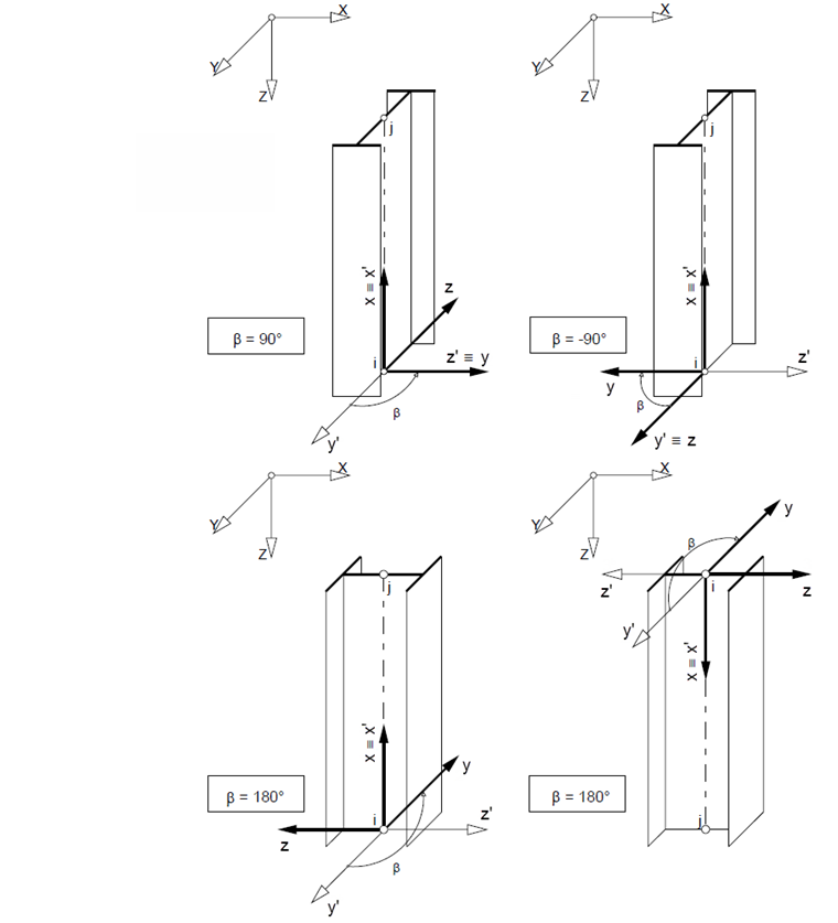
The member can be rotated about the longitudinal axis of this member by using the rotation angle β. A positive angle corresponds to a rotation of the axis y in the direction of the axis z. It is important for the axis orientation whether the member is defined from top to bottom or from bottom to top (see Figure 04 and Figure 05).
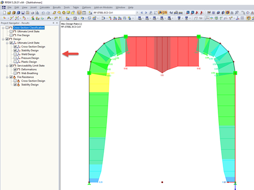
Member Axis Modification Due to Member Position
If the axis “jumps around” in the case of a supporting continuous member, the cause is usually the automatic classification of the member position: The position of the continuous member is classified as “vertical” and the position of the connected members as “general”. The general member position applies if there are (minimally) different X and Y coordinates for the definition nodes of a member, so the member is slightly inclined.
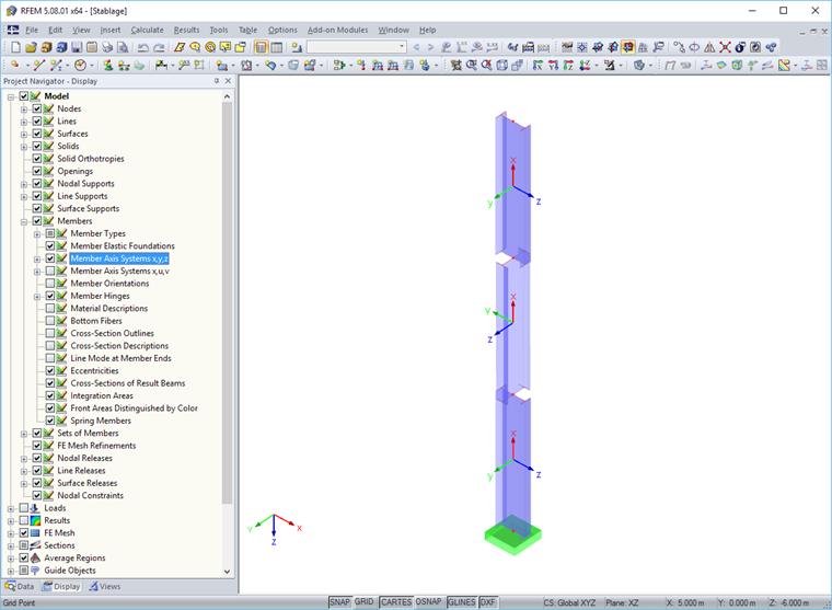
Variable axes complicate the definition of local member loads and imperfections. They also influence the symbols and signs of the internal forces.
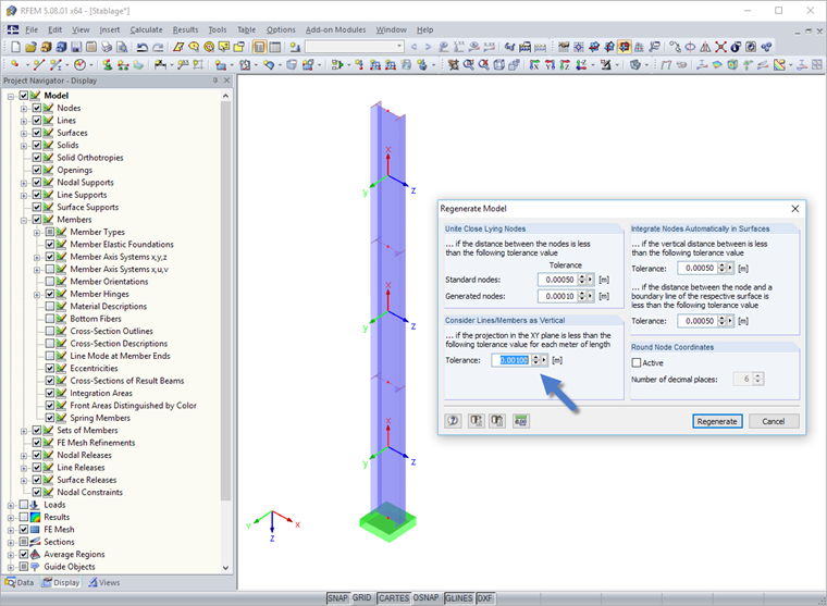
When importing a DXF model in particular, it may happen that the X and Y coordinates of the definition nodes are not identical to all decimal places. This can be corrected by manual adjustment. A better way is to compensate the deviations with the “Regenerate model” program option, which also allows user‑defined tolerances.
Summary
In a 3D model, the member orientation is important for the model stiffness as well as for assigning local loads. When entering a member, the local axis system is automatically defined on the basis of the definition nodes. It is then possible to adjust the axis orientation by using a member rotation angle. RFEM and RSTAB allow you to check the member position quickly and reliably in 3D rendering.