Consideration of Load Increment Factor β
If there is a wall corner or a wall end subjected to the punching shear design in RF-PUNCH Pro, the add-on module determines the punching load from the non- smoothed distribution of shear forces along the critical perimeter. When determining the punching load, the non-rotationally symmetrical distribution of the shear force along the critical perimeter is already considered by applying the maximum value of this shear force to determine the punching load. This consideration is set as a default setting for the analysis of wall corners and ends so there is always the load increasing factor β of 1.00.
As an alternative, it is also possible to select the smoothed distribution of the shear force along the critical perimeter for the determination of the punching load. In order to consider the non-rotationally symmetrical load or distribution of the shear force along the critical perimeter, the load increase factor β should be considered according to EN 1992‑1‑1 [1], Section 6.4.3 in this case.
In RF-PUNCH Pro, the determination of the load increasing factor using the full plastic shear distribution according to 6.4.3 (3) is preset by default. In the case of rigidly fixed systems with span width differences less than 25% in the adjacent fields, the values of β from EN 1992‑1‑1, Fig. 6.21N [1] can also be used. The German Annex [2] to EN 1992-1-1 supplements Fig. 6.21N by the constant factors for wall corners with β = 1.20 and for wall ends with β = 1.35.
Both methods for determining the load increasing factor β have been available since the release of the RF-PUNCH Pro add-on module. The load increasing factor determination by the program has been extended with the option of the user-defined specification of the value of β. As of the release of the RFEM version 5.09.01, there is also the option to determine the load increasing factor by a sector model available in RF-PUNCH Pro.
Sector Model
On one hand, using the maximum value of the shear force at the critical perimeter is the most accurate method for determining the design value of the punching load; on the other hand, it is also the method that is most susceptible to singularity effects.
According to the explanation of the German Committee for Structural Concrete [3], the following approaches are available for determining the β factor according to DIN EN 1997‑1‑1 (with NA):
- More precise methods with the plastic shear stress distribution
- Sector model (or load application area)
- Constant factors for stiffened systems with approximately the same spans
In Book 600 of the German Committee for Reinforced Concrete (Dafstb) [3], in the section on 6.3.4, the sector model is described as an alternative method for determining the load increasing factor β. In this case, the load increasing factor β can be determined by dividing the maximum sector force νEd,i by the mean value of the shear force νEd,m determined by using the critical perimeter. For this, see Fig. H6-34 in [3] with the following equation:
The determination of the load shears explained in [3] is omitted when applying the sector model in RF-PUNCH Pro, since the actual load distribution is included in the internal forces in surfaces in RFEM. Therefore, only the average shear force along the critical perimeter and the average shear force within the respective sectors are required to determine the load increasing factor according to the equation described above.
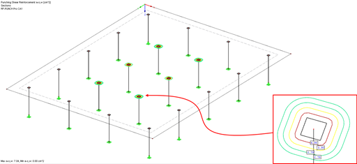
According to [3], the load application area ALE is to be divided into i-load application sectors Ai, and the recommendation is to use three to four sectors per quadrant. RF-PUNCH Pro meets this recommendation and always divides each quadrant into four sectors. When determining the load increasing factor β for a single support, 16 sectors are thus obtained. (see Image 03).
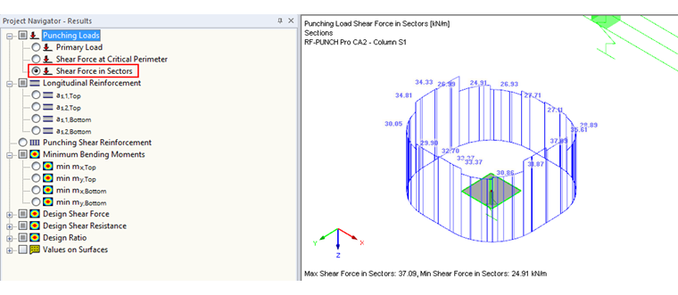
The number of sectors at the respective punching shear points is automatically determined by the module and obtained with respect to the geometry or the position of the punching shear location.
Shear Force in Individual Sectors
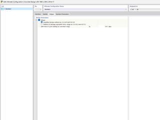
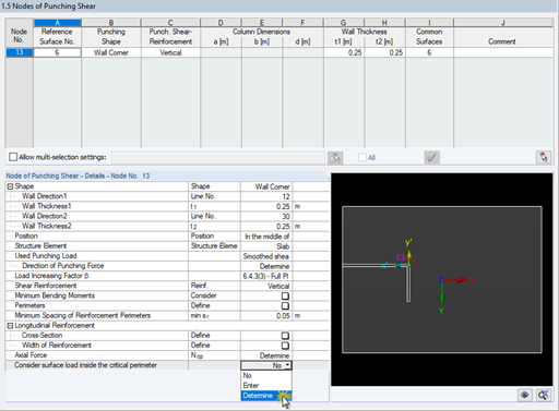
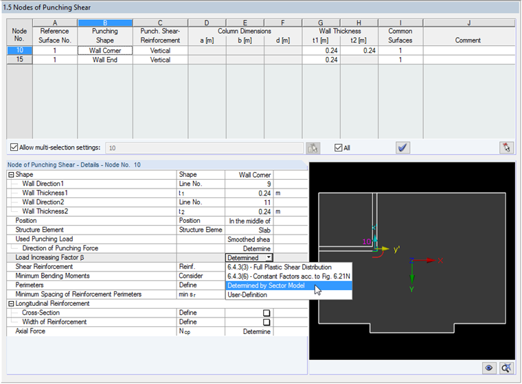
The following example illustrates the determination of the load increasing factor for a wall corner. The following setting is made in Window 1.5:
- smoothed shear force over the critical perimeter
- load increasing factor β determined by sector model
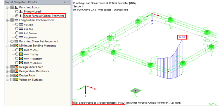
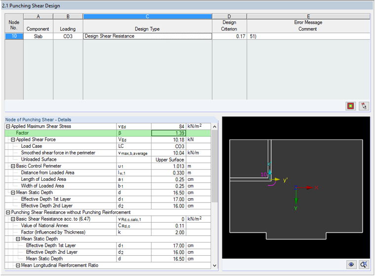
Result Window 2.1 shows the load increasing factor of β = 1.39 for this example. In order to follow this value from the RF-PUNCH Pro calculation, you can choose between the result display options "Shear Force at Critical Perimeter" and "Shear Force in Sectors" in the Results Navigator.
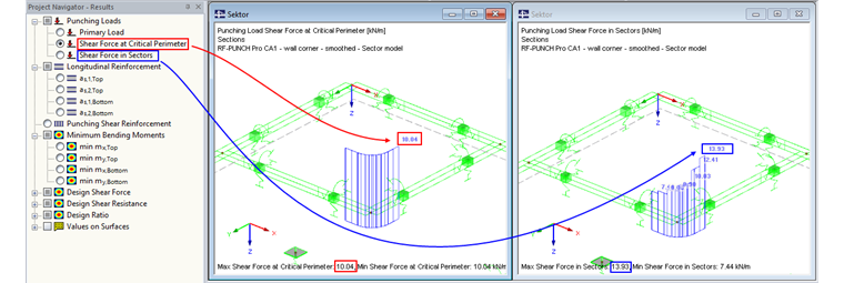
In our example, the average value of the shear force over the entire critical perimeter is 10.04 kN/m and the maximum value of the average shear forces within the individual sectors is 13.93 kN/m. From this, the following results:
Load increasing factor β = 13.93 kN/m / 10.04 kN/m = 1.39
The determined value of β is displayed in Window 2.1.
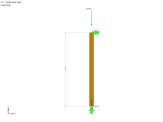
This example describes the determination of the load increasing factor on a wall corner by deriving the punching load from the shear forces in the critical perimeter. As an alternative, it is possible to select the "Sector Model" method if the punching load is taken from the axial force of a column or a support force of a nodal support, for example.