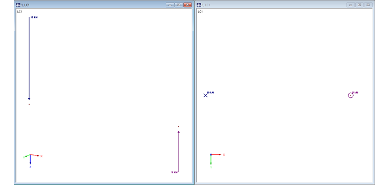
Concentrated Load
In a spatial view, a point load is displayed as a vector (a line with an arrow) above the reference node or point. The vector length indicates the respective size and the arrow shows the direction of the load. When looking in the direction of the load axis, the load symbol changes accordingly. The program displays a crossed circle when looking in the direction of the load and a circle with a center point when looking in the opposite direction. To specify the load size exactly, you can additionally write a numeric value next to the spatial and planar symbols.
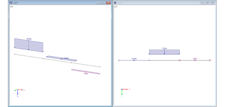
Line Load
A line load is treated in a similar way as a concentrated load. The spatial display of a load on lines or members is represented by a framed array of vectors (a line with an arrow) above the assigned line. The vector length indicates (qualitatively) the size and the arrow indicates the direction of the load. A frame with optional shading around the load vectors should illustrate the line reference. When looking in the direction of the load axis, the load symbol changes accordingly. The program displays a crossed circle when looking in the direction of the load, and a circle with a center point when looking in the opposite direction. To specify the load size exactly, you can additionally write a numeric value next to the combined load symbol.
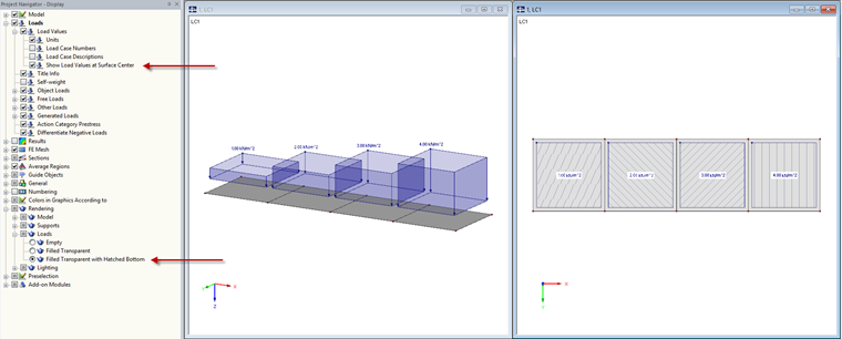
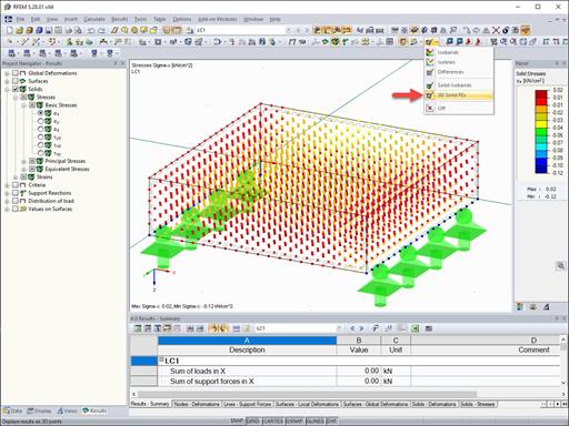
Flat Load
The spatial display of flat loads is a further development of the line load. In the spatial display, a framed vector set represents the boundary lines of the load. The vector length indicates (qualitatively) the size and the arrow indicates the direction of the load. A frame with optional shading around the load vectors should illustrate the outer edge of the surface load. In summary, this results in a block-shaped display of the load. When looking in the direction of the load, the rotating vectors are not converted into a crossed or dotted circle, but the line polygon is displayed around the arrow with optional shading or hatching. The hatching is set in such a way that each load size uses a separate hatching type. To specify the load size exactly, you can additionally write the numerical value at the the edge or in the middle of the load symbol.


Dlubal_KohlA_]_LI.jpg?mw=350&hash=ee8d38f1c4853d80307fa156c159b5e78a3fdca9)


.png?mw=600&hash=49b6a289915d28aa461360f7308b092631b1446e)
