Structure
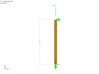
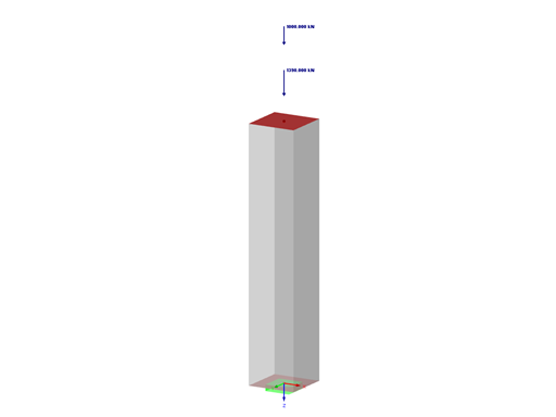
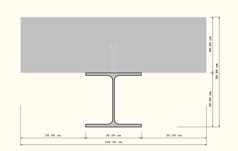
The composite beam is supported as a single‑span beam at a length of 15 m. In reality, the composite is created using headed stud shear connectors that are welded every 1.25 m. The self‑weight is assumed as loading (Figure 01).
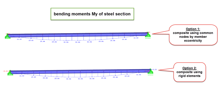
Option 1: Composite Using Common Nodes by Member Eccentricity
Both cross-section elements are modeled each as (2 ⋅) 12 ⋅ 1.25 m long member elements (member type beam). Since both cross‑sections are initially located on the same line, the "Allow Double Members" function under "Edit" has to be activated so that they can be considered separately, but are still supported at the same end node. The corresponding member eccentricity has to be assigned to all 2 ⋅ 12 member elements so that the top edge of the steel section is equal to the bottom edge of the concrete cross‑section (Figure 02).
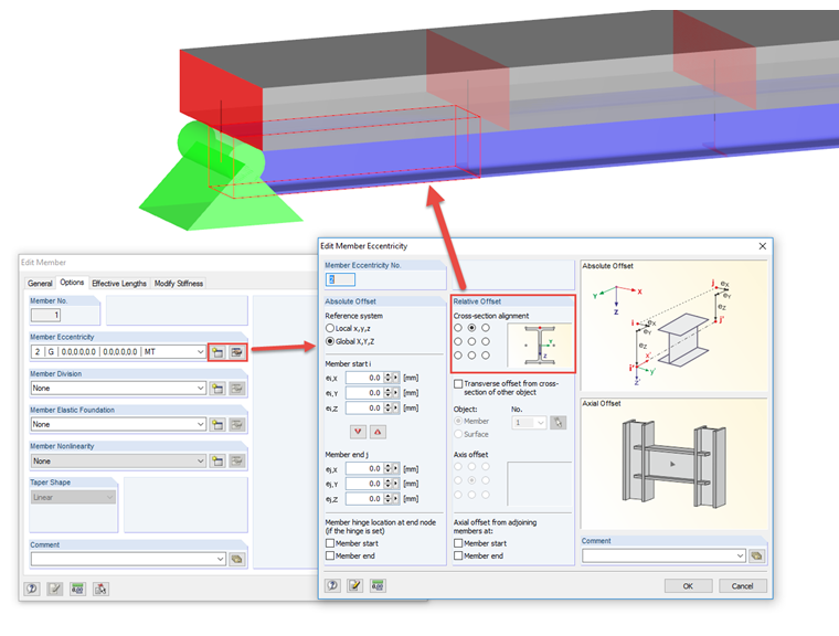
This way, the twelve individual composite elements are connected to each other at their respective member start and member end.
Option 2: Composite Using Rigid Elements
The same modeling takes place here for the elements as for Option 1, with the difference that no eccentricities are assigned to the cross‑sections, but both member cross‑sections are on two separate lines. To create twelve composite elements of the total of 24 member elements, the individual cross‑sections are connected with each other by rigid members. At both supports the rigid member is divided into two members each so that the nodal supports are located in the composite joint, as in Option 1. The support is carried out with rigid members (Figure 03).
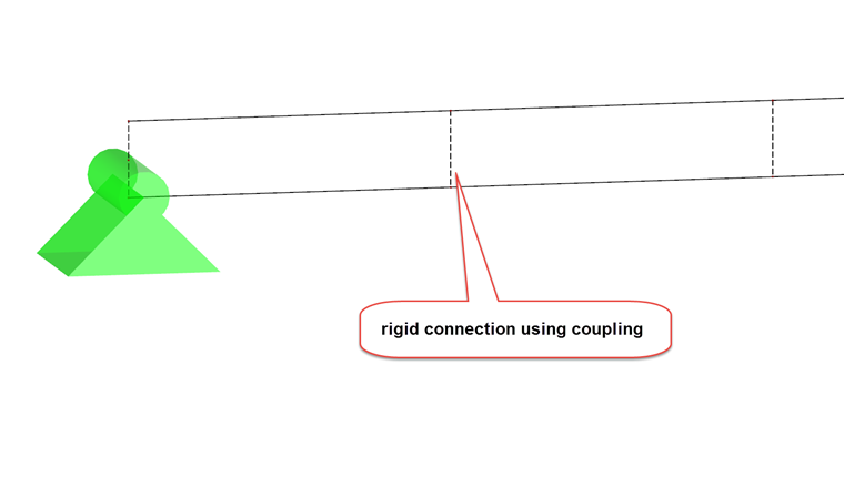
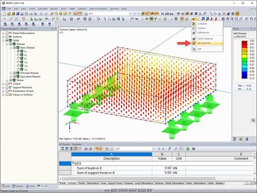
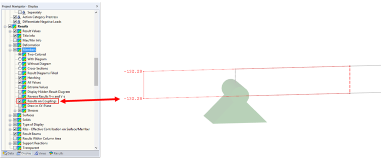
The rigid members connect both complete cross‑sections in the same way as an eccentricity. This option offers the possibility to modify the stiffnesses of the rigid members similarly to the existing headed stud shear connectors at their ends, or even to replace them with other member types. In addition, there is the option to see the internal forces of the couplings (rigid members). Therefore, it is necessary to activate the "Results on Couplings" option in the Display Navigator under "Results" → "Deformation" → "Members" (Figure 04).
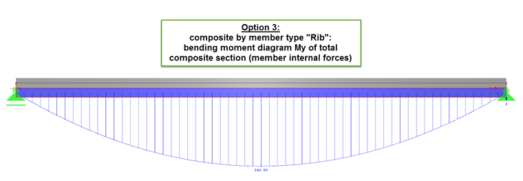
Option 3: Composite by Member Type "Rib"
This option is based on a completely different modeling. The concrete cross‑section is modeled as a surface, the steel cross‑section as a rib. The eccentricity of the rib can be defined within the "Edit Rib" dialog box on the +z-side of the surface. To obtain the same support situation as in Option 1 and Option 2, the surface (and thus, automatically, also the rib) can be connected on both sides to the support with the rigid member, from its central axis to its +z‑side. Furthermore, to obtain internal forces for the complete cross‑section, the option "On Members Addition of Surface Components" has to be activated in the Display Navigator → "Results" → "Members" → "Ribs - Effective Contribution on Surface/Member"). Find more information about the member type rib in the corresponding FAQs.
Summary
Whereas the first two options are a kind of framework model and thus bending moments jump favorably due to the couplings, the third option represents an ideal composite cross-section. Due to the internal forces integrated over the concrete surface, the internal forces have a different size than in the first two options and have to be evaluated differently (Figures 05 and 06).
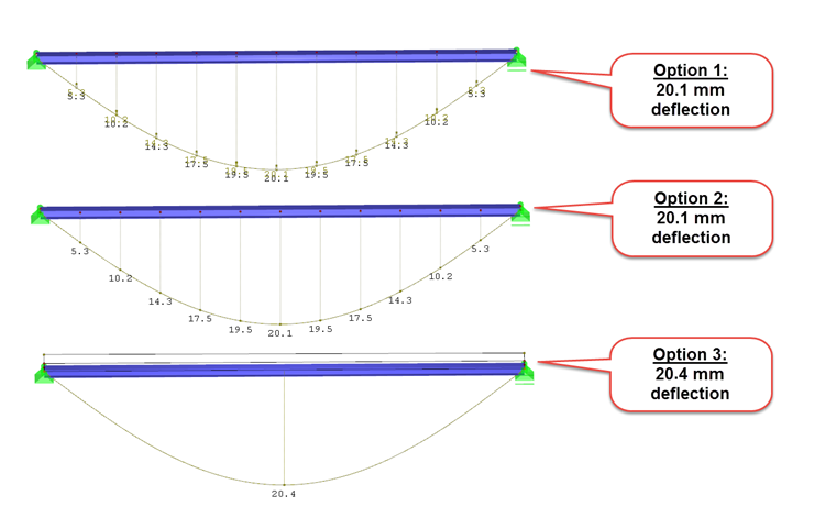
However, a comparison of the deflection reveals that all three options can be used for modeling (Figure 07).
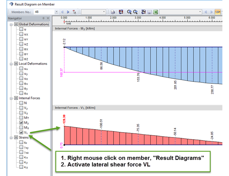
Moreover, concerning the shear effect between concrete cross‑section and steel cross‑section, it can be stated that the results are comparable. The longitudinal shear force VL is displayed when activating the internal force VL under "Result Diagram" (right‑click the rib) (Figure 08).
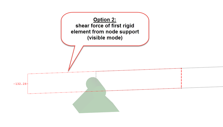
This compares to the shear force of the rigid members of Option 2 (Figure 09).
| Internal forces and deflections in comparison | Option 1 | Option 2 | Option 3 |
|---|---|---|---|
| My [kNm] | 32.64 | 32.64 | 240.5 |
| u [mm] | 20.1 | 20.1 | 20.4 |
| VL [kN] | 132.3 | 132.3 | 128.3 |