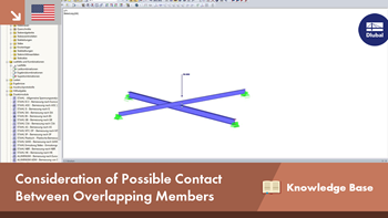
We recommend dividing the two beams at the level of the crossing to realize the situation described above so that a new node is generated at these locations. If the "Connect Lines / Members" function in the shortcut menu is deactivated, it must be applied manually for both crossing members. They are then divided at the previously inserted node, but are still each one continuous member.
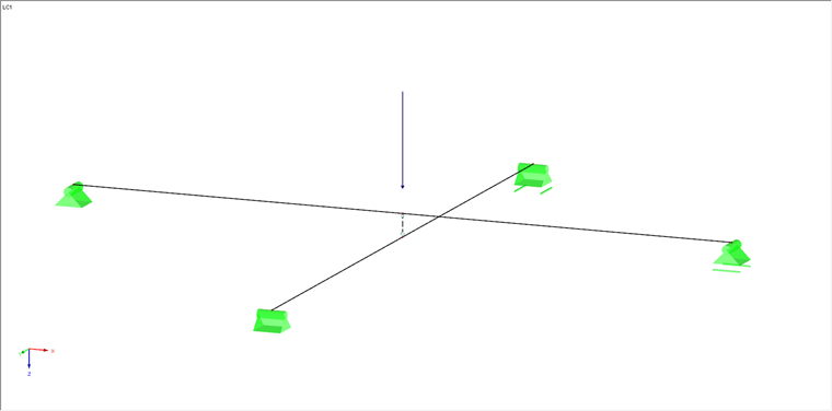
In the next step, the two crossing members are connected by a short rigid member between the two new nodes.
The rigid member ideally contains a moment hinge at the member start and the member end, so that no moments are transmitted at this location.
In the last step, the following two conditions have to be defined at the connection and at the inserted rigid member:
- Failure under tension (for example, in case of a lifting upper member)
- Force transmission under compression only at contact of the two members
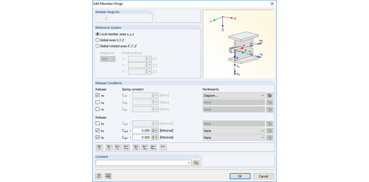
Both conditions can be defined at one of the two member end hinges of the rigid member as a nonlinearity using the diagram. It is necessary to open the "Edit Member End Hinge" dialog box first.
After selecting the local member axes as the reference system and thus the axial release ux is activated, the diagram to the right can be selected as a nonlinearity. The "Nonlinearity - Diagram - Member End Hinge ux" dialog box is opened using the "Edit Nonlinearity of Translational Release N" button.
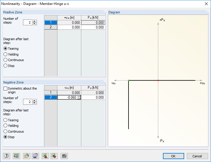
The failure under tension is defined in the positive zone of the normal force. This means Only the "Tearing" option (after the last step) is activated here. In the negative zone, the "Symmetric around the origin" option is deactivated first so that the following two steps can be defined:
The above-mentioned 6 cm of "slipping" is the distance between the top edge of the upper beam and the bottom edge of the lower beam and applies, of course, only to this example. This means that it has to be adapted according to the distance of the two beams. The respective value is determined as follows:
ux = (length of the rigid member) - (half beam depth of top member) - (half beam depth of bottom member)
"Stop" has to be selected as the diagram after the last step so that the force has its full effect after reaching the defined deformation. The dialog boxes can both be confirmed successively with [OK].
Graphical and Numerical Control
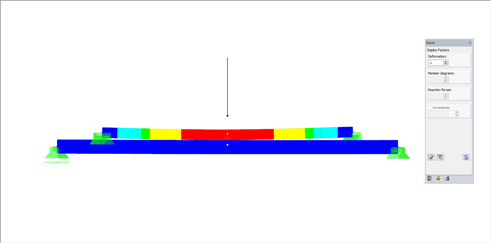
After the nonlinearity has been defined successfully and the first results have been generated, the scaling factor has to be taken into account when looking at the deformations (see panel, "Factors" tab, "Display Factors - Deformation"). Graphical control of the defined nonlinearity is only reasonable with the display factor "1" for a possible contact of the members (compression), since an exaggerated display of the deformation may look, for example, as if the top member is bending more than the bottom member.
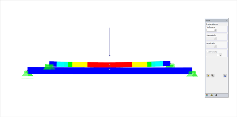
Related to the original position, the deflection of the top member is, of course, always bigger than the deflection of the bottom member when the members have contact. Moreover, besides the graphical control, a check of the deformation values is recommended to ensure that the corresponding nonlinearity has been defined correctly. If both members have contact, the following applies:
(Deformation of the top member) - (amount of the defined slippage ux) = (deformation of the bottom member)
A corresponding compression normal force should be assigned to the rigid member in case of a contact of both beams. The corresponding option has to be activated in the Display Navigator (see FAQ 002080).