General
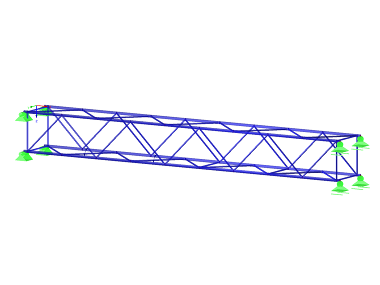
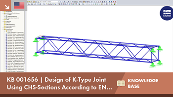
Slender truss structures made of closed cross-sections are popular in architecture. Due to computer-aided production of cuts and connection geometries, it is possible also to have complex spatial nodes. This technical article deals with the design of a K-node. The node definition and the design, in particular, are described in detail.

Details of the Model
Material: S355
Chord cross-section: RO 108x6.3 | DIN 2448, DIN 2458
Strut cross-section: RO 60.3x4 | DIN 2448, DIN 2458
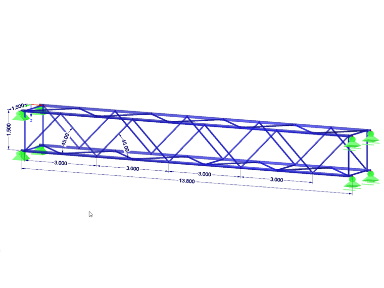
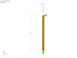
Dimensions: see graphic
Assigning the Node to the Joint Type
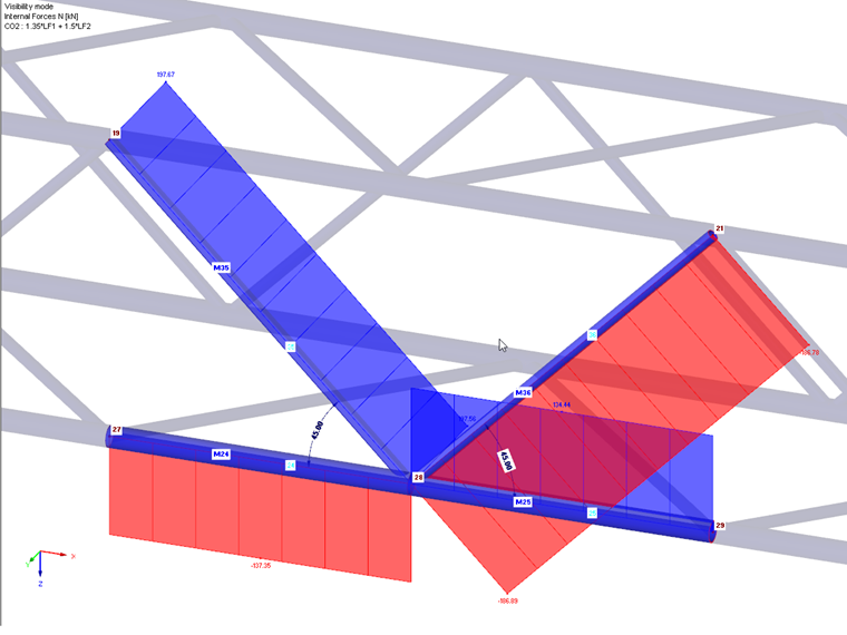
The connection type for a hollow section node is not only defined by the geometry, but also by the orientation of the axial forces in the struts. In our example, there is a tensile force in member no. 35 (strut 1) and a compression force in member no. 36 (strut 2) on node no. 28 to be designed. Given this distribution of internal forces and moments, the joint type is a K-node. If there was compression or tension in both struts, the connection type would be a Y-node.
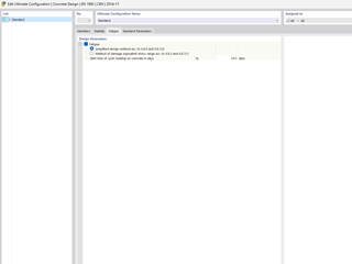
Checking the Validity Limits
Compliance with the validity limits is crucial for any design. The ratio of the diameters of struts and chords is important. If it is not in the range of 0.2 ≤ di / do ≤ 1.0, it is impossible to perform the design. The diameter ratio di / do is also referred to as β. The European standard EN 1993-1-8 [1] specifies in Table 7.1 the validity limits for struts and chord members, as well as a limitation of the struts' overlap. If you want to have a gap between the struts, a minimum dimension of g ≥ t1 + t2 must be observed, too. t is the respective wall thickness of the struts. Structural components subjected to compression also need to be classified into cross-section classes 1 or 2. A corresponding check is carried out according to EN 1993-1-1 [2], Chapter 5.5.
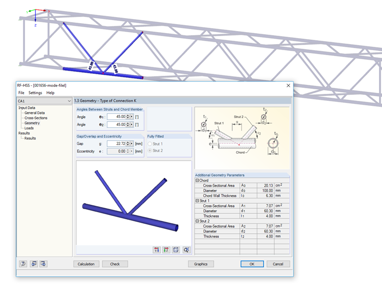
Design Process
In our example, the connection meets the validity limits according to Table 7.1. Therefore, it is sufficient according to EN 1993-1-8, Chapter 7.4.1 (2) to analyze the chord member for flange failure and punching shear.
Flange failure of a chord member due to axial force according to EN 1993-1-8, Table 7.2, Row 3.2:
Determination of diameter-wall ratio γ
| γ | Ratio of the chord member's width or diameter to the double of its wall thickness |
| Ψ2,i | Beiwert für quasi-ständige Werte der veränderlichen Einwirkungen i |
| t0 | Wall thickness of chord cross-section |
γ = 8.57
Determination of factor kg
| kg | Factor for nodal connections with a gap g |
| γ | Ratio of the chord member's width or diameter to the double of its wall thickness |
| e | Euler's number |
| g | Gap width between struts of a K or N joint |
| t0 | Wall thickness of chord cross-section |
kg = 1.72
Determination of the chord tension coefficient kp
| kp | Chord prestress coefficient |
| np | Ratio |
| fp | Value of acting compressive stress in chord member without stresses due to components of strut forces at connection parallel to chord |
| fy | Yield strength |
| Np | Starting axial compressive force in chord |
| A0 | Cross-sectional area of chord member |
| M0 | Secondary moment from eccentricity |
| W0 | Elastic section modulus of chord cross-section |
fp is the chord tension from the axial force Np and the additional moment from eccentricity. Since there are compression and tension in the chord, it is assumed that Np = 0. Furthermore, the eccentricity of the joint is so small that an additional moment from any eccentric connection of the struts does not have to be considered. Thus, the auxiliary factor fp is zero. The sign rule for compression and tension forces in RFEM and RSTAB differs from those of the European standard EN 1993-1-8. Therefore, the formula for kp has been adjusted.
kp = 1.0
Determination of the allowable limit internal force NRd
| N1,Rd | Design value of axial force resistance of connection for strut 1 |
| kg | Factor for nodal connections with a gap g |
| kp | Chord prestress coefficient |
| fy0 | Yield strength of material of a chord member |
| t0 | Wall thickness of chord cross-section |
| θ1 | Enclosed angle between strut 1 and chord member |
| d1 | Total diameter of strut 1 |
| d0 | Total diameter of chord member |
| yM5 | Partial safety factor |
| N2,Rd | Design value of axial force resistance of connection for strut 2 |
| θ2 | Enclosed angle between strut 2 and chord member |
N1,Rd = N2,Rd = 257.36 kN
N1,Ed / N1,Rd = 197.56 / 257.36 = 0.77 < 1.0
N2,Ed / N2,Rd = 186.89 / 257.36 = 0.73 < 1.0
Punching the chord member due to axial force according to EN 1993-1-8, Table 7.2, Row 4:
Determination of the allowable limit internal force NRd
| Ni,Rd | Design value of axial force resistance of connection for structural component i |
| fy0 | Yield strength of material of a chord member |
| t0 | Wall thickness of chord cross-section |
| π | Circle number |
| di | Total diameter for CHS components i |
| θi | Enclosed angle between strut i and chord member |
| γM5 | Partial safety factor |
N1,Rd = N2,Rd = 417.58 kN
N1,Ed / N1,Rd = 197.56 / 417.58 = 0.47 < 1.0
N2,Ed / N2,Rd = 186.89 / 417.58 = 0.45 < 1.0
Flange failure of a chord member due to moment Mop according to EN 1993-1-8, Table 7.5, Row 2:
This design is only relevant for 3D structures where moments may also occur from the truss plane.
Determination of the allowable limit internal force Mop,Rd
| Mop,i,Rd | Design value of moment resistance of connection for bending out of plane of structural system for structural component i |
| fy0 | Yield strength of material of a chord member |
| t0 | Wall thickness of chord cross-section |
| di | Total diameter for CHS components i |
| θi | Enclosed angle between strut i and chord member |
| β | Ratio of mean diameters or mean widths of strut and chord |
| kp | Chord prestress coefficient |
| yM5 | Partial safety factor |
Mop,1,Rd = Mop,2,Rd = 5.92 kNm
Mop,1,Ed / Mop,1,Rd = 0.08 / 5.92 = 0.01 < 1.0
Mop,2,Ed / Mop,2,Rd = 0.01 / 5.92 = 0.00 < 1.0
Flange failure of a chord member due to moment Mip according to EN 1993-1-8, Table 7.5, Row 1:
Determination of the allowable limit internal force Mip,Rd
| Mip,i,Rd | Design value of moment resistance of connection for bending in plane of structural system for structural component i |
| fy0 | Yield strength of material of a chord member |
| t0 | Wall thickness of chord cross-section |
| di | Total diameter for CHS components i |
| θi | Enclosed angle between strut i and chord member |
| γ | Ratio of the chord member's width or diameter to the double of its wall thickness |
| β | Ratio of mean diameters or mean widths of strut and chord |
| kp | Chord prestress coefficient |
| γM5 | Partial safety factor |
Mip,1,Rd = Mip,2,Rd = 9.53 kNm
Mip,1,Ed / Mip,1,Rd = 0.37 / 9.53 = 0.04 < 1.0
Mip,2,Ed / Mip,2,Rd = 0.14 / 9.53 = 0.01 < 1.0
Punching the chord member due to moment Mop according to EN 1993-1-8, Table 7.5, Row 3.2:
This design is only relevant for 3D structures where moments may also occur from the truss plane.
Determination of the allowable limit internal force Mop,Rd
| Mop,i,Rd | Design value of moment resistance of connection for bending out of plane of structural system for structural component i |
| fy0 | Yield strength of material of a chord member |
| t0 | Wall thickness of chord cross-section |
| di | Total diameter for CHS components i |
| θi | Enclosed angle between strut i and chord member |
| yM5 | Partial safety factor |
Mop,1,Rd = Mop,2,Rd = 8.70 kNm
Mop,1,Ed / Mop,1,Rd = 0.08 / 8.70 = 0.01 < 1.0
Mop,2,Ed / Mop,2,Rd = 0.01 / 8.70 = 0.00 < 1.0
Punching the chord member due to moment Mip according to EN 1993-1-8, Table 7.5, Row 3.1:
Determination of the allowable limit internal force Mip,Rd
| Mip,i,Rd | Design value of moment resistance of connection for bending in plane of structural system for structural component i |
| fy0 | Yield strength of material of a chord member |
| t0 | Wall thickness of chord cross-section |
| di | Total diameter for CHS components i |
| θi | Enclosed angle between strut i and chord member |
| yM5 | Partial safety factor |
Mip,1,Rd = Mip,2,Rd = 7.33 kNm
Mip,1,Ed / Mip,1,Rd = 0.37 / 7.33 = 0.05 < 1.0
Mip,2,Ed / Mip,2,Rd = 0.14 / 7.33 = 0.02 < 1.0
Interaction conditions according to EN 1993-1-8, Chapter 7.4.2, Equation 7.3:
In this design step, the struts are designed for the shared loading from axial force and bending. Currently, only bending perpendicular to the truss plane is considered here.
| Ni,Ed | Design value of acting axial force for structural component i |
| Ni,Rd | Design value of axial force resistance of connection for structural component i |
| Mop,i,Ed | Design value of acting moment out of plane of structural system for structural component i |
| Mop,i,Rd | Design value of moment resistance of connection for bending out of plane of structural system for structural component i |
Summary
The technical article shows that the design for a K-node is not trivial. With the RF-/HSS add-on module, Dlubal offers a tool for designing all nodal types defined in the European standard, for CHS as well as SHS and RHS sections.


.png?mw=600&hash=49b6a289915d28aa461360f7308b092631b1446e)


